HP DL360 Fully-Buffered DIMM technology in HP ProLiant servers - Page 3
HP DL360 - ProLiant - G3 Manual
 |
UPC - 613326948835
View all HP DL360 manuals
Add to My Manuals
Save this manual to your list of manuals |
Page 3 highlights
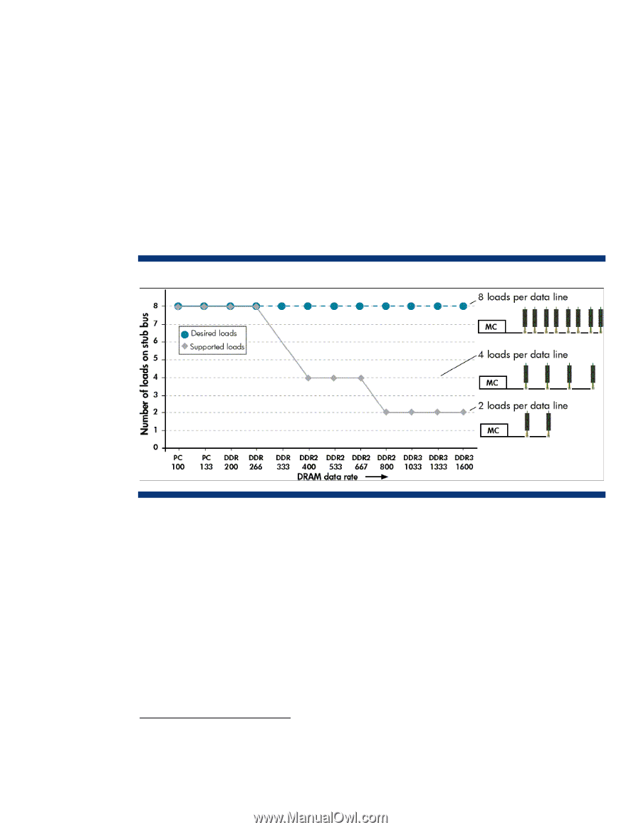
Each stub-bus connection creates an impedance discontinuity that negatively affects signal integrity. In addition, each DIMM creates an electrical load on the bus. The electrical load accumulates as DIMMs are added. These factors decrease the number DIMMs per channel that can be supported as the bus speed increases. For example, Figure 2 shows the number of loads supported per channel at data rates ranging from PC 100 to DDR-3 1600. Note that the number of supported loads drops from eight to two as data rates increase to DDR2 800. Increasing the number of channels to compensate for the drop in capacity per channel was not a viable option due to increased cost and board complexity. System designers had two options: limit memory capacity so that fewer errors occur at higher speeds, or use slower bus speeds and increase the DRAM density. For future generations of high-performance servers, neither option was acceptable. Future generations of servers require an improved memory architecture to achieve higher memory bandwidth and capacity. Consequently, JEDEC3 developed the Fully-Buffered DIMM specification, a serial interface that eliminates the parallel stub-bus topology and allows higher memory bandwidth while maintaining or increasing memory capacity. Figure 2. Maximum number of loads per channel based on DRAM data rate. 3 The Joint Electron Device Engineering Council (JEDEC) is the semiconductor engineering standardization body of the Electronic Industries Alliance. HP works with JEDEC memory vendors and chipset developers during memory technology development to ensure that new memory products fulfill customer needs in regards to reliability, cost, and backward compatibility. 3
-
 1
1 -
 2
2 -
 3
3 -
 4
4 -
 5
5 -
 6
6 -
 7
7 -
 8
8 -
 9
9 -
10
 |
 |