HP Designjet 230 Service Manual - Page 83
Removing the PinchĆArm Sensor, Removing the DriveĆRoller Gear, the spittoon.
 |
View all HP Designjet 230 manuals
Add to My Manuals
Save this manual to your list of manuals |
Page 83 highlights
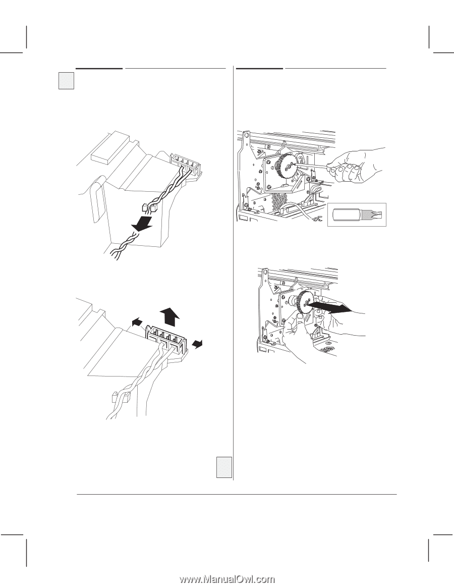
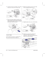
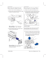
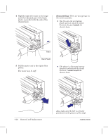
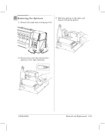
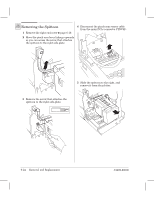
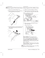
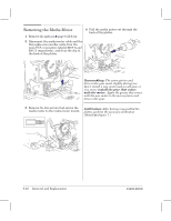
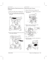
330 350C Removing the PinchĆArm Sensor Removing the DriveĆRoller Gear 1 Remove the spittoon ' page 6Ć24. 2 Release the pinchĆarm sensor cable from the indicated clip on the spittoon. 1 Remove the spittoon ' page 6Ć23/6Ć24. 2 Remove the two screws that secure the driveĆroller gear to the driveĆroller shaft. Torx-10 3 Gently press the two indicated tabs to the side and lift the pinchĆarm sensor from the spittoon. 3 Remove the driveĆroller gear from the driveĆroller shaft. The gear may be stiff. C4699Ć90000 Reassembling: The worm pinion and driveĆroller gear mesh slightly during use. Don't install a new motor and an old gear, or vice versa: install the gear that comes with the motor. Apply the grease that comes with the new motor to the worm pinion and driveĆroller gear. Reassembling: Push the gear onto the shaft as far as it will go. Align the holes on the gear with the holes on the shaft. 330 350C Always calibrate the XĆaxis after reassembling the motor or the gear ' page 7Ć8. Removal and Replacement 6Ć25
-
 1
1 -
2
-
3
-
4
-
5
-
6
-
7
-
8
-
9
-
10
-
11
-
12
-
13
-
14
-
15
-
16
-
17
-
18
-
19
-
20
-
21
-
22
-
23
-
24
-
25
-
26
-
27
-
28
-
29
-
30
-
31
-
32
-
33
-
34
-
35
-
36
-
37
-
38
-
39
-
40
-
41
-
42
-
43
-
44
-
45
-
46
-
47
-
48
-
49
-
50
-
51
-
52
-
53
-
54
-
55
-
56
-
57
-
58
-
59
-
60
-
61
-
62
-
63
-
64
-
65
-
66
-
67
-
68
-
69
-
70
-
71
-
72
-
73
-
74
-
75
-
76
-
77
-
 78
78 -
 79
79 -
 80
80 -
 81
81 -
 82
82 -
 83
83 -
 84
84 -
 85
85 -
 86
86 -
 87
87 -
 88
88 -
89
-
90
-
91
-
92
-
93
-
94
-
95
-
96
-
97
-
98
-
99
-
100
-
101
-
102
-
103
-
104
-
105
-
106
-
107
-
108
-
109
-
110
-
111
-
112
-
113
-
114
-
115
-
116
-
117
-
118
-
119
-
120
-
121
-
122
-
123
-
124
-
125
-
126
-
127
-
128
-
129
-
130
-
131
-
132
-
133
-
134
-
135
-
136
-
137
-
138
-
139
-
140
-
141
-
142
-
143
-
144
-
145
-
146
-
147
-
148
-
149
-
150
-
151
-
152
-
153
-
154
-
155
-
156
-
157
-
158
-
159
-
160
-
161
-
162
-
163
-
164
-
165
-
166
-
167
-
168
-
169
-
170
-
171
-
172
-
173
-
174
-
175
-
176
-
177
-
178
-
179
-
180
-
181
-
182
-
183
-
184
-
185
-
186
-
187
-
188
-
189
-
190
-
191
-
192
-
193
-
194
-
195
-
196
-
197
-
198
-
199
-
200
-
201
-
202
-
203
-
204
-
205
-
206
-
207
-
208
-
209
-
210
-
211
-
212
-
213
-
214
-
215
-
216
-
217
-
218
-
219
-
220
-
221
-
222
-
223
-
224
-
225
-
226
-
227
-
228
-
229
-
230
-
231
-
232
-
233
-
234
-
235
-
236
-
237
-
238
-
239
-
240
-
241
-
242
-
243
-
244
-
245
-
246
-
247
-
248
-
249
-
250
-
251
-
252
-
253
-
254
-
255
-
256
-
257
-
258
-
259
-
260
-
261
-
262
-
263
-
264
-
265
-
266
-
267
-
268
 |
 |