HP Designjet L28500 HP Designjet L28500 Printer Series - Site preparation guid - Page 10
Branch circuit breakers, Power cables, WARNING, CAUTION
 |
View all HP Designjet L28500 manuals
Add to My Manuals
Save this manual to your list of manuals |
Page 10 highlights
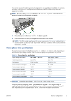
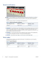
Branch circuit breakers NOTE: The circuit breakers must meet the requirements of the printer and should be in accordance with the Electrical Code requirements of the local jurisdiction of the country where the equipment is installed. The printer requires a branch circuit breaker for the three-phase line. Table 2-4 Branch circuit breaker specifications Input voltage (line to line) 380-415 V~ (-10%+6%) 200-240 V~ (±10%) Three-phase 4 poles, 30/32 A 3 poles, 50 A WARNING! Ensure that the printer's built-in Residual Current Circuit Breaker (also known as Ground Fault Circuit Interrupter) operates in the case of a leakage current fault to the product chassis, even when an isolation device (such as an isolating transformer) is used to supply power to the printer. An IT power distribution system should not be used. WARNING! Ensure that mains fault current is adequate for proper operation of the supplementary circuit breakers incorporated in the printer (10 kA rated interrupting capacity). CAUTION: Ensure that the input voltage is within the printer's rated voltage range. Power cables A three-phase power cable is not provided with the printer. The cables that you use must meet the following minimum specifications. Table 2-5 Cable specifications Input voltage (line to line) 380-415 V~ (-10%+6%) Configuration 5 wires, L1/L2/L3/N/PE Wire Strained Cu, minimum 4 mm² or 10 AWG 200-240 V~ (±10%) 4 wires, L1/L2/L3/PE Strained Cu, minimum 6 mm² or 8 AWG 6 Chapter 2 Site preparation requirements ENWW
-
 1
1 -
2
-
3
-
4
-
 5
5 -
 6
6 -
 7
7 -
 8
8 -
 9
9 -
 10
10 -
 11
11 -
 12
12 -
 13
13 -
 14
14
 |
 |
