HP Dv7-1243cl HP Pavilion dv7 Entertainment PC - Maintenance and Service Guide - Page 67
Optical drive, Remove the Phillips PM2.5×5.0 screw
 |
View all HP Dv7-1243cl manuals
Add to My Manuals
Save this manual to your list of manuals |
Page 67 highlights
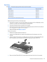
5. Release the webcam/microphone module (1) from the display enclosure as far as the webcam/ microphone module cable allows. 6. Disconnect the webcam/microphone module cable (2) from the webcam/microphone module. 7. Remove the webcam/microphone module. Reverse this procedure to install the webcam/microphone module. Optical drive NOTE: All optical drive spare part kits include an optical drive bezel and bracket. Description Blu-ray Disc ROM Drive with SuperMulti DVD±R/RW Double-Layer DVD±RW and CD-RW SuperMulti Double-Layer Combo Drive with LightScribe DVD±RW and CD-RW SuperMulti Double-Layer Combo Drive Spare part number 480461-001 480459-001 480458-001 Before removing the optical drive, follow these steps: 1. Shut down the computer. If you are unsure whether the computer is off or in Hibernation, turn the computer on, and then shut it down through the operating system. 2. Disconnect all external devices connected to the computer. 3. Disconnect the power from the computer by first unplugging the power cord from the AC outlet and then unplugging the AC adapter from the computer. 4. Remove the battery (see Battery on page 54). Remove the optical drive: 1. Position the computer with the front toward you. 2. Remove the Phillips PM2.5×5.0 screw (1) that secures the optical drive to the computer. Component replacement procedures 57
-
 1
1 -
2
-
3
-
4
-
5
-
6
-
7
-
8
-
9
-
10
-
11
-
12
-
13
-
14
-
15
-
16
-
17
-
18
-
19
-
20
-
21
-
22
-
23
-
24
-
25
-
26
-
27
-
28
-
29
-
30
-
31
-
32
-
33
-
34
-
35
-
36
-
37
-
38
-
39
-
40
-
41
-
42
-
43
-
44
-
45
-
46
-
47
-
48
-
49
-
50
-
51
-
52
-
53
-
54
-
55
-
56
-
57
-
58
-
59
-
60
-
61
-
 62
62 -
 63
63 -
 64
64 -
 65
65 -
 66
66 -
 67
67 -
 68
68 -
 69
69 -
 70
70 -
 71
71 -
 72
72 -
73
-
74
-
75
-
76
-
77
-
78
-
79
-
80
-
81
-
82
-
83
-
84
-
85
-
86
-
87
-
88
-
89
-
90
-
91
-
92
-
93
-
94
-
95
-
96
-
97
-
98
-
99
-
100
-
101
-
102
-
103
-
104
-
105
-
106
-
107
-
108
-
109
-
110
-
111
-
112
-
113
-
114
-
115
-
116
-
117
-
118
-
119
-
120
-
121
-
122
-
123
-
124
-
125
-
126
-
127
-
128
-
129
-
130
-
131
-
132
-
133
-
134
-
135
-
136
-
137
-
138
-
139
-
140
-
141
-
142
-
143
-
144
-
145
-
146
-
147
-
148
-
149
-
150
-
151
-
152
-
153
-
154
-
155
-
156
-
157
-
158
-
159
-
160
-
161
-
162
-
163
-
164
-
165
-
166
-
167
-
168
-
169
-
170
-
171
-
172
-
173
-
174
-
175
-
176
-
177
-
178
-
179
-
180
-
181
-
182
-
183
-
184
-
185
-
186
 |
 |
