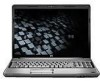
HP Dv7-1243cl HP Pavilion dv7 Entertainment PC - Maintenance and Service Guide - Page 87
CAUTION, replacement instructions for computer models equipped with BrightView display assemblies.
 |
View all HP Dv7-1243cl manuals
Add to My Manuals
Save this manual to your list of manuals |
Page 87 highlights
2. Remove the wireless antenna cables (2) from the routing channels in the top cover. CAUTION: The display assembly will be unsupported when the following screws are removed. To prevent damage to the display assembly, support it before removing the screws. 3. Remove the three Phillips PM2.5×13.0 screws (1) and the three Phillips PM2.5×6.0 screws (2) that secure the display assembly to the computer. 4. Remove the display assembly (3). NOTE: Steps 5 through 24 provide display assembly internal component removal information for computer models equipped with AntiGlare display assemblies. See steps 25 through 40 for display assembly internal component removal information for computer models equipped with BrightView display assemblies. NOTE: See Webcam/microphone module on page 56 for webcam/microphone module replacement instructions for computer models equipped with BrightView display assemblies. 5. If it is necessary to replace the display enclosure or any of the display assembly internal components, remove the two rubber screw covers (1) on the display bezel lower edge. The rubber screw covers are available in the Display Rubber Kit, spare part number 495896-001. Component replacement procedures 77
-
 1
1 -
2
-
3
-
4
-
5
-
6
-
7
-
8
-
9
-
10
-
11
-
12
-
13
-
14
-
15
-
16
-
17
-
18
-
19
-
20
-
21
-
22
-
23
-
24
-
25
-
26
-
27
-
28
-
29
-
30
-
31
-
32
-
33
-
34
-
35
-
36
-
37
-
38
-
39
-
40
-
41
-
42
-
43
-
44
-
45
-
46
-
47
-
48
-
49
-
50
-
51
-
52
-
53
-
54
-
55
-
56
-
57
-
58
-
59
-
60
-
61
-
62
-
63
-
64
-
65
-
66
-
67
-
68
-
69
-
70
-
71
-
72
-
73
-
74
-
75
-
76
-
77
-
78
-
79
-
80
-
81
-
 82
82 -
 83
83 -
 84
84 -
 85
85 -
 86
86 -
 87
87 -
 88
88 -
 89
89 -
 90
90 -
 91
91 -
 92
92 -
93
-
94
-
95
-
96
-
97
-
98
-
99
-
100
-
101
-
102
-
103
-
104
-
105
-
106
-
107
-
108
-
109
-
110
-
111
-
112
-
113
-
114
-
115
-
116
-
117
-
118
-
119
-
120
-
121
-
122
-
123
-
124
-
125
-
126
-
127
-
128
-
129
-
130
-
131
-
132
-
133
-
134
-
135
-
136
-
137
-
138
-
139
-
140
-
141
-
142
-
143
-
144
-
145
-
146
-
147
-
148
-
149
-
150
-
151
-
152
-
153
-
154
-
155
-
156
-
157
-
158
-
159
-
160
-
161
-
162
-
163
-
164
-
165
-
166
-
167
-
168
-
169
-
170
-
171
-
172
-
173
-
174
-
175
-
176
-
177
-
178
-
179
-
180
-
181
-
182
-
183
-
184
-
185
-
186
 |
 |
