HP Dx2250 Hardware Reference Guide - dx2250 MT - Page 19
Removing a 5.25\, Removing the Computer Access Panel and, Front Bezel,
 |
UPC - 883585243983
View all HP Dx2250 manuals
Add to My Manuals
Save this manual to your list of manuals |
Page 19 highlights
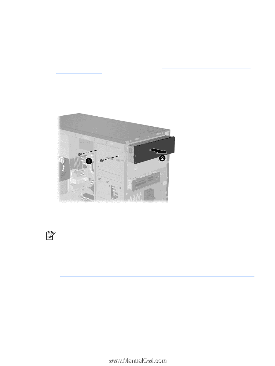
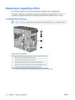
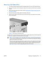
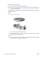
Removing a 5.25" Optical Drive 1. Turn off the computer properly through the operating system, then turn off any external devices. 2. Disconnect the power cord from the power outlet and the computer, and disconnect any external devices. 3. Remove the access panel and front bezel. Refer to Removing the Computer Access Panel and Front Bezel on page 3. 4. Disconnect the power and data cables from the back of the drive. 5. Remove the two retainer screws that secure the drive to the bay (1) then slide the drive forward and out of the bay (2). Figure 2-9 Removing a 5.25" External Drive To install a drive, reverse the removal procedure. Be sure to install a guide screw on the front right side of a new drive. The guide screw helps secure the drive in place. NOTE If you are installing a drive in the bottom 5.25" drive bay, remove the metal shield that covers the bay by pressing inward on the silver tab on the left side of the chassis then pulling the shield out from the front of the chassis. There are a total of eight extra guide/retainer screws on the front of the chassis behind the bezel. Four have 6-32 standard threads and four have M3 metric threads. Standard screws are used for hard drives and have a silver finish. Metric screws are used for all other drives and have a black finish. Be sure to install the appropriate guide screws into the drive. ENWW Replacing or Upgrading a Drive 13
-
 1
1 -
2
-
3
-
4
-
5
-
6
-
7
-
8
-
9
-
10
-
11
-
12
-
13
-
 14
14 -
 15
15 -
 16
16 -
 17
17 -
 18
18 -
 19
19 -
 20
20 -
 21
21 -
 22
22 -
 23
23 -
 24
24 -
25
-
26
-
27
-
28
-
29
 |
 |