HP Integrity Superdome 2 16-socket LIFT-O-FLEX® 17000 SP 400 Manual - Page 2
Lift-O-Flex™ 17000 SP 400 Manual, TABLE OF CONTENTS
 |
View all HP Integrity Superdome 2 16-socket manuals
Add to My Manuals
Save this manual to your list of manuals |
Page 2 highlights
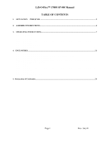
Lift-O-Flex™ 17000 SP 400 Manual TABLE OF CONTENTS 1. LIFT-O-FLEX 17000 SP 400 ...2 1.1 Warranty 3 2. ASSEMBLY INSTRUCTIONS...4 2.1 Assembly 4 3. OPERATING INSTRUCTIONS...7 3.1 3.1.1 3.1.2 3.1.3 3.1.4 3.2 3.3 Operating 7 Charging 7 Handlebar 8 Lifting 8 Transport 8 Troubleshooting 9 Maintenance 10 4. ENCLOSURES ...11 4.1 Electrical wiring 11 4.1.1 Wiring for Intermediate Member with brake motor 11 4.1.2 Wiring of Motor Controller 12 4.3.3 Wiring of Remote Control 13 4.3.4 Intermediate Section 14 4.3.5 Legs 15 4.4.6 Mast 16 4.4.7 Handle 17 4.4.8 Brake rod 18 4.4.9 Power Pack 19 4.4.10 Lifter Check List 20 5. Declaration of Conformity...21 Page 1 Rev. July 01
-
 1
1 -
 2
2 -
 3
3 -
 4
4 -
 5
5 -
 6
6 -
 7
7 -
 8
8 -
9
-
10
-
11
-
12
-
13
-
14
-
15
-
16
-
17
-
18
-
19
-
20
-
21
-
22
 |
 |

Lift-O-Flex™ 17000 SP 400 Manual
Page 1
Rev. July 01
TABLE OF CONTENTS
1.
LIFT-O-FLEX
17000 SP 400
............................................................................................................................
2
1.1
Warranty
..........................................................
3
2.
ASSEMBLY INSTRUCTIONS
............................................................................................................................
4
2.1
Assembly
..........................................................
4
3.
OPERATING INSTRUCTIONS
..........................................................................................................................
7
3.1
Operating
.........................................................
7
3.1.1
Charging
..........................................................
7
3.1.2
Handlebar
.........................................................
8
3.1.3
Lifting
...........................................................
8
3.1.4
Transport
.........................................................
8
3.2
Troubleshooting
...................................................
9
3.3
Maintenance
......................................................
10
4.
ENCLOSURES
.....................................................................................................................................................
11
4.1
Electrical wiring
................................................
11
4.1.1
Wiring for Intermediate Member with brake motor
..................
11
4.1.2
Wiring of Motor Controller
.......................................
12
4.3.3
Wiring of Remote Control
.........................................
13
4.3.4
Intermediate Section
.............................................
14
4.3.5
Legs
.............................................................
15
4.4.6
Mast
.............................................................
16
4.4.7
Handle
...........................................................
17
4.4.8
Brake rod
........................................................
18
4.4.9
Power Pack
.......................................................
19
4.4.10 Lifter Check List
................................................
20
5.
Declaration of Conformity
....................................................................................................................................
21