HP Integrity Superdome 2 16-socket LIFT-O-FLEX® 17000 SP 400 Manual - Page 5
Lift-O-Flex, SP 400 Manual, Assembly instructions
 |
View all HP Integrity Superdome 2 16-socket manuals
Add to My Manuals
Save this manual to your list of manuals |
Page 5 highlights
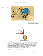
Lift-O-Flex 17000 SP 400 Manual 2. Assembly instructions Each lifter is to be delivered in modules and will be shipped in cardboard box(s). Components are as indicated below. Leg-RH Leg-LH Lift Mast Intermediate Section Handlebar w/Remote Controller Brake Rod End-Effector Fixed Forks Electronic Power Pack with ground cable attached 2.1 Assembly Assembly instructions 1. Place the intermediate section without lift motor attached and stand it on its end on the floor. Make sure that the mast collar hold down clip is facing to the rear of the lifter. (See picture on next page). Take the four flathead hex screws (M 8 x 30 mm), take one of the legs and mount the leg to the frame with the 5mm Allen wrench enclosed. 2. Turn the intermediate section with one leg attached on its side and insert the brake rod (item 13 or 14) at a forward angle (the wheels are now in the locked position) into the hexagon hole situated above the wheel. Take the next leg and insert the brake rod into its hexagon hole located above the wheel and secure the leg with the screws as described above. Check to make sure both rear casters are in the locked position prior to bolting final leg to intermediate section. Next, slip the lift motor intermediate section into the leg channels provided at the front of the lifter base. Remove quick disconnect pin from rear bracket prior to sliding lift motor intermediate section into position. Lock it into place by re-inserting the quick disconnect pin. Page 4 Rev July 01
-
 1
1 -
 2
2 -
 3
3 -
 4
4 -
 5
5 -
 6
6 -
 7
7 -
 8
8 -
 9
9 -
 10
10 -
 11
11 -
12
-
13
-
14
-
15
-
16
-
17
-
18
-
19
-
20
-
21
-
22
 |
 |
