HP PageWide 377 OfficeJet Pro X and PageWide 300 400 500 series - Shipping Ins - Page 5
Part no.: D3Q21-67004 - SERV ASSY-Print bar Restraint 500 series
 |
View all HP PageWide 377 manuals
Add to My Manuals
Save this manual to your list of manuals |
Page 5 highlights
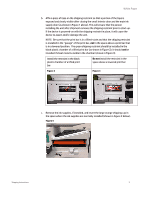
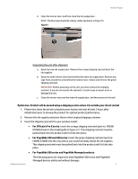
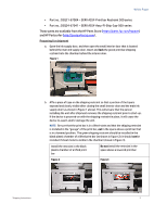
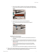
White Paper • Part no.: D3Q21-67004 - SERV ASSY-Print bar Restraint 500 series • Part no.: D3Q24-67041 - SERV ASSY-Assy-FI-Ship-Cap-500-series These parts are available from the HP Parts Store (https://parts.hp.com/hpparts) and HP Partsurfer (http://partsurfer.hp.com). Preparing for shipment a. Open the ink supply door, and then open the small interior door that is located behind the main ink supply door. Insert and lock the green print bar shipping restraint into the chamber behind the interior door. Figure 1 b. Affix a piece of tape on the shipping restraint so that a portion of the tape is exposed and clearly visible after closing the small interior door and the main ink supply door (as shown in Figure 1 above). This will ensure that the person installing the unit after shipment removes the shipping restraint prior to start-up. If the device is powered-on with the shipping restraint in place, it will cause the device to assert and/or damage the unit. NOTE: Be sure that the print bar is in a lifted-state and that the shipping restraint is installed in the "garage" of the print bar, not in the space above a print bar that is in a lowered position. The green shipping restraint should be installed in the black plastic chamber of a lifted print bar (as shown in Figure 2); it should not be installed if sheet metal is visible in the chamber (shown in Figure 3). Install the restraint in the black plastic chamber of a lifted print bar Do not install the restraint in the space above a lowered print bar Figure 2 Figure 3 Shipping Instructions 5
-
 1
1 -
 2
2 -
 3
3 -
 4
4 -
 5
5 -
 6
6 -
 7
7
 |
 |
