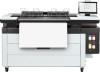
HP PageWide XL 4700 Assembly Instructions
HP PageWide XL 4700 Manual
 |
View all HP PageWide XL 4700 manuals
Add to My Manuals
Save this manual to your list of manuals |
HP PageWide XL 4700 manual content summary:
- HP PageWide XL 4700 | Assembly Instructions - Page 1
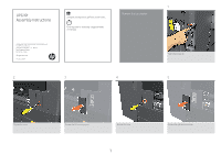
UPG Kit Assembly Instructions © Copyright 2021 HP Development Company, L.P. Large Format Division Camí de Can Graells 1-21 · 08174 Sant Cugat del Vallès Barcelona · Spain All rights reserved Printed in XXX 2 people are - HP PageWide XL 4700 | Assembly Instructions - Page 2
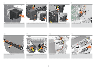
6 7 8 9 Remove the paper output stacker covers, one from each side. Remove six screws and the lateral cover at front panel side. Remove three screws and lateral cover at other side. Unplug the connector cable. 10 11 12 13 Remove the diverter valve cover. Unscrew two M4 x 8 mm screws ( - HP PageWide XL 4700 | Assembly Instructions - Page 3
14 15 16 17 With the door open, extract the top hooks and remove the module. Loosen six M4 x 8mm screws at each side (twelve total). Unplug the two sensors. 18 19 Replace the pinches beam Remove the structure. 20 Unplug the two cables. Do not remove or loosen the screws highlighted in - HP PageWide XL 4700 | Assembly Instructions - Page 4
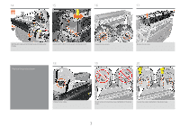
21 22 23 Remove the screws highlighted in the above image. Remove the paper output pinch system. 24 Remove the diverter Perform the removal process in reverse to install the new paper output pinch beam. 25 26 Remove the two screws. Remove the E-box top cover. 4 Remove the eight gusset - HP PageWide XL 4700 | Assembly Instructions - Page 5
27 28 29 Remove the eight diverter valve cover screws. Disconnect the three cables. 30 Intergrate the adjustment plate Remove the diverter valve. 31 Slot the X-adjusment plate into the right assembly. Fix the X-adjusment plate with an M4 screw in middle of slot. 5 - HP PageWide XL 4700 | Assembly Instructions - Page 6
32 33 34 Assemble the accessory sensors 35 Slot the two sensor safety assemblies into the spring-grounding microswitches. Printer right side sensor: Follow 1 and 2 in the above image to attach the previous assembly with the accessory switch holder, then assemble the sensor grounding. Printer - HP PageWide XL 4700 | Assembly Instructions - Page 7
39 40 41 Assemble the diverter Attach the other assembly into the left side of the printer structure., then repeat steps 36, 37 and 38 to connect it. Push the cable clamp into place, and connect the cable. 42 43 44 Insert the diverter valve. Important: Ensure that the brackets highlighted in - HP PageWide XL 4700 | Assembly Instructions - Page 8
45 46 47 Assemble the top stacker 48 Install the structure, making sure that the pin matches on the front panel side. Tighten the six M4 x 8mm screws at each side (twelve total). With the door open, insert the top hooks and install the module. 49 50 51 Plug in the sensor connector. Plug - HP PageWide XL 4700 | Assembly Instructions - Page 9
52 53 54 55 Plug in the connector cable. 56 Attach the lateral cover at the front panel side with six screws. Attach the lateral cover at the other side with three screws. Attach the paper output stacker covers, one on each side. 57 58 Install the accessory interface Insert the seventeen - HP PageWide XL 4700 | Assembly Instructions - Page 10
Utilities > Enterprise UPG Kit. Install the HP PageWide XL 4X00 Accessory Upgrade Kit licence. Insert the USB dongle into the USB port. To recalibrate the beam, see the section: Paper-output path adjustable beam in the Service Manual. 10 © Copyright 2021HP Development Company, L.P. The
-
 1
1 -
 2
2 -
 3
3 -
 4
4 -
 5
5 -
 6
6 -
 7
7 -
8
-
9
-
10
 |
 |
1
© Copyright 2021 HP Development Company, L.P.
Large Format Division
Camí de Can Graells 1-21 · 08174
Sant Cugat del Vallès
Barcelona · Spain
All rights reserved
Printed in XXX
UPG Kit
Assembly Instructions
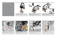
2 people are required to perform certain tasks.
70
Time required for assembly is approximately
70 minutes .
Remove the top stacker
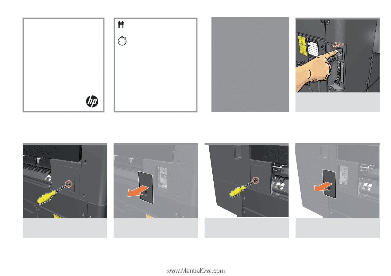
Switch the printer off.
Remove the screw.
Remove the right accessory cover.
Remove the screw.
Remove the left accessory cover.
1
2
3
4
5