HP PageWide XL 4700 Assembly Instructions - Page 6
Assemble the accessory sensors
 |
View all HP PageWide XL 4700 manuals
Add to My Manuals
Save this manual to your list of manuals |
Page 6 highlights
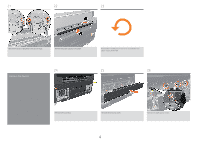
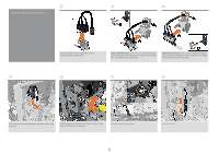
32 33 34 Assemble the accessory sensors 35 Slot the two sensor safety assemblies into the spring-grounding microswitches. Printer right side sensor: Follow 1 and 2 in the above image to attach the previous assembly with the accessory switch holder, then assemble the sensor grounding. Printer left side sensor: Follow 1 and 2 in the above image to attach the previous assembly with the accessory switch holder, then assemble the sensor grounding. 36 37 38 Attach the previous assembly into the right side of the printer structure. Attach the sensor grounding to the accessory switch holder, then install the previous assembly. Push the cable clamp into place. 6 Connect the cable.
-
 1
1 -
 2
2 -
 3
3 -
 4
4 -
 5
5 -
 6
6 -
 7
7 -
 8
8 -
 9
9 -
 10
10
 |
 |

6
35
36
37
38
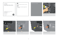
Assemble the accessory sensors
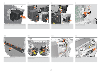
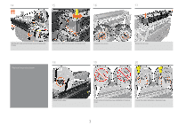
Attach the sensor grounding to the accessory switch holder,
then install the previous assembly.
Push the cable clamp into place.
Attach the previous assembly into the right side of the printer
structure.
Printer left side sensor:
Follow 1 and 2 in the above image to
attach the previous assembly with the accessory switch holder,
then assemble the sensor grounding.
Printer right side sensor:
Follow 1 and 2 in the above image to
attach the previous assembly with the accessory switch holder,
then assemble the sensor grounding.
Slot the two sensor safety assemblies into the
spring-grounding microswitches.
Connect the cable.
33
34
32