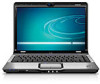
HP Pavilion dv2000 HP Pavilion dv2000 Notebook PC Maintenance and Service Guid
HP Pavilion dv2000 - Entertainment Notebook PC Manual
 |
View all HP Pavilion dv2000 manuals
Add to My Manuals
Save this manual to your list of manuals |
HP Pavilion dv2000 manual content summary:
- HP Pavilion dv2000 | HP Pavilion dv2000 Notebook PC Maintenance and Service Guid - Page 1
HP Pavilion dv2000 Notebook PC Document Part Number: 417981-002 April 2007 This guide is a troubleshooting reference used for maintaining and servicing the computer. It provides comprehensive information on identifying computer features, components, and spare parts; troubleshooting computer problems - HP Pavilion dv2000 | HP Pavilion dv2000 Notebook PC Maintenance and Service Guid - Page 2
Windows, and Windows of Advanced Micro Devices, Inc. Bluetooth is a trademark HP shall not be liable for technical or editorial errors or omissions contained herein. Maintenance and Service Guide HP Pavilion dv2000 Notebook PC Second Edition: April 2007 First Edition: June 2006 Document Part - HP Pavilion dv2000 | HP Pavilion dv2000 Notebook PC Maintenance and Service Guid - Page 3
surface, such as an adjoining optional printer, or a soft surface, such as pillows or rugs or clothing, to block airflow. Also, do not allow the AC adapter to contact the skin or a soft surface, such as pillows or rugs or clothing, during operation. The computer and the - HP Pavilion dv2000 | HP Pavilion dv2000 Notebook PC Maintenance and Service Guid - Page 4
Design Overview 1-21 2 Troubleshooting 2.1 Setup Utility in Windows XP 2-1 Using the Setup Utility 2-2 Setup Utility Menus 2-6 2.2 Setup Utility in Windows Vista 2-9 Using the Setup Utility 2-9 Setup Utility Menus 2-13 2.3 Troubleshooting Flowcharts 2-15 Maintenance and Service Guide iv - HP Pavilion dv2000 | HP Pavilion dv2000 Notebook PC Maintenance and Service Guid - Page 5
Components 3-20 3.4 Mass Storage Devices 3-22 3.5 Plastics Kit 3-24 3.6 Cable Kit 3-25 3.7 Miscellaneous 3-26 3.8 Sequential Part Number Listing 3-29 4 Removal and Replacement Preliminaries 4.1 Tools Required 4-1 4.2 Service Considerations 4-2 Plastic Parts 4-2 Cables and Connectors - HP Pavilion dv2000 | HP Pavilion dv2000 Notebook PC Maintenance and Service Guid - Page 6
5-58 5.18 Bluetooth Module 5-60 5.19 USB Board 5-62 5.20 Speaker Assembly 5-64 5.21 Display Lid Switch Module 5-66 5.22 System Board 5-70 5.23 Power Connector Cable 5-73 5.24 ExpressCard Assembly 5-75 5.25 Fan/Heat Sink Assembly 5-78 5.26 Processor 5-86 Maintenance and Service Guide vi - HP Pavilion dv2000 | HP Pavilion dv2000 Notebook PC Maintenance and Service Guid - Page 7
Contents 6 Specifications A Screw Listing B Backup and Recovery in Windows XP C Backup and Recovery in Windows Vista D Display Component Recycling E Connector Pin Assignments F Power Cord Set Requirements Index vii Maintenance and Service Guide - HP Pavilion dv2000 | HP Pavilion dv2000 Notebook PC Maintenance and Service Guid - Page 8
The HP Pavilion dv2000 Notebook PC offers advanced modularity, Intel® Core™ Duo, Core Solo, and Celeron® processors or AMD Turion™ 64 Mobile Technology and Mobile AMD Sempron™ processors, and extensive multimedia support. HP Pavilion dv2000 Notebook PC Maintenance and Service Guide 1-1 - HP Pavilion dv2000 | HP Pavilion dv2000 Notebook PC Maintenance and Service Guid - Page 9
-GHz) ❏ Mobile AMD Sempron 3200+ (1.60-GHz) ■ 14.1-inch WXGA (1280 × 768) TFT display with over 16.7 million colors, varying by computer model 1-2 Maintenance and Service Guide - HP Pavilion dv2000 | HP Pavilion dv2000 Notebook PC Maintenance and Service Guid - Page 10
Card IEEE 802.11b and 802.11b/g WLAN device ■ Support for one ExpressCard ■ External 65-watt or 90-watt AC adapter with 3-wire power cord ■ 6-cell or 12-cell Li-Ion battery ■ Stereo speakers with volume up and down buttons ■ Integrated Web camera (select models only) ■ Integrated microphone (select - HP Pavilion dv2000 | HP Pavilion dv2000 Notebook PC Maintenance and Service Guid - Page 11
information). 3. Wait approximately 5 minutes. 4. Replace the RTC battery and reassemble the computer. 5. Connect AC power to the computer. Do not reinsert any batteries at this time. 6. Turn on the computer. All passwords and all CMOS settings have been cleared. 1-4 Maintenance and Service Guide - HP Pavilion dv2000 | HP Pavilion dv2000 Notebook PC Maintenance and Service Guid - Page 12
power management features: ■ Standby ■ Hibernation ■ Setting customization by the user ■ Hotkeys for setting the level of performance ■ Battery calibration ■ Lid switch standby/resume ■ Power button ■ Advanced Configuration and Power Management (ACPM) compliance Maintenance and Service Guide - HP Pavilion dv2000 | HP Pavilion dv2000 Notebook PC Maintenance and Service Guid - Page 13
is turned off when all batteries in the computer are fully charged. If the computer is not plugged into an external power source, the light stays off until the battery reaches a low-battery condition. Blinking: The hard drive or optical drive is being accessed. 1-6 Maintenance and Service Guide - HP Pavilion dv2000 | HP Pavilion dv2000 Notebook PC Maintenance and Service Guid - Page 14
light Blue: An integrated wireless device, such as a wireless local area network (LAN) device and/or a Bluetooth® device, is turned on. Red: An integrated wireless device is turned off. Consumer infrared lens Links the computer to the HP Remote Control. Audio-in (microphone) jack Connects an - HP Pavilion dv2000 | HP Pavilion dv2000 Notebook PC Maintenance and Service Guid - Page 15
Right-Side Components Item 1 2 3 4 Table 1-2 Right-Side Components Component Function Optical drive Reads an optical disc. USB ports (2) Connect optional USB devices. RJ-11 (modem) jack Connects a modem cable. Power connector Connects an AC adapter. 1-8 Maintenance and Service Guide - HP Pavilion dv2000 | HP Pavilion dv2000 Notebook PC Maintenance and Service Guid - Page 16
Product Description The external components on the left side of the computer are shown below and described in Table 1-3. Left-Side Components Maintenance and Service Guide 1-9 - HP Pavilion dv2000 | HP Pavilion dv2000 Notebook PC Maintenance and Service Guid - Page 17
an optional S-Video device such as a television Memory Stick (MS), Memory Stick Pro (MSP), xD-Picture Card (XD), xDPicture Card (XD) Type M. Digital Media Slot light On: A digital card is being accessed. ExpressCard slot Supports optional ExpressCard/54 cards. 1-10 Maintenance and Service Guide - HP Pavilion dv2000 | HP Pavilion dv2000 Notebook PC Maintenance and Service Guid - Page 18
Product Description The keyboard components on the computer are shown below and described in Table 1-4. Keyboard Components Maintenance and Service Guide 1-11 - HP Pavilion dv2000 | HP Pavilion dv2000 Notebook PC Maintenance and Service Guid - Page 19
the pointer. Arrow keys Move the cursor around the screen. Embedded numeric keypad keys (15) Can be used like the keys on an external numeric keypad. num lock key Enables numeric lock, turns on the embedded numeric keypad, and turns on the num lock light. 1-12 Maintenance and Service Guide - HP Pavilion dv2000 | HP Pavilion dv2000 Notebook PC Maintenance and Service Guid - Page 20
Product Description The top components on the computer are shown below and described in Table 1-5. Top Components, Part 1 Maintenance and Service Guide 1-13 - HP Pavilion dv2000 | HP Pavilion dv2000 Notebook PC Maintenance and Service Guid - Page 21
4 5 6 7 8 Table 1-5 Top Components, Part 1 Component Function Caps lock light On: Caps lock is on. Power button When the computer is ■ Off, press to has stopped responding and Microsoft® Windows® shutdown procedures cannot be used, press and hold the power button for at least 5 Service Guide - HP Pavilion dv2000 | HP Pavilion dv2000 Notebook PC Maintenance and Service Guid - Page 22
Product Description The top components on the computer are shown below and described in Table 1-6. Top Components, Part 2 Maintenance and Service Guide 1-15 - HP Pavilion dv2000 | HP Pavilion dv2000 Notebook PC Maintenance and Service Guid - Page 23
1-6 Top Components, Part 2 Component Function software is not installed, the computer starts in Windows. ■ In hibernation, opens QuickPlay to start a DVD in the optical drive. If the QuickPlay software is not installed, the computer resumes from hibernation. 1-16 Maintenance and Service Guide - HP Pavilion dv2000 | HP Pavilion dv2000 Notebook PC Maintenance and Service Guid - Page 24
the computer are shown below and described in Table 1-7. Top Components, Part 3 Item 1 2 3 4 Table 1-7 Top Components, Part 3 Component Function Previous/Rewind Button When a disc is playing in the optical drive, press to stop the current disc activity. Maintenance and Service Guide 1-17 - HP Pavilion dv2000 | HP Pavilion dv2000 Notebook PC Maintenance and Service Guid - Page 25
Components Component Function TouchPad on/off button Enables/disables the TouchPad. TouchPad Moves the pointer and selects or activates items on the screen. Left and right TouchPad buttons Function like the left and right buttons on an external mouse. TouchPad scroll zone Scrolls upward or - HP Pavilion dv2000 | HP Pavilion dv2000 Notebook PC Maintenance and Service Guid - Page 26
Bottom Components Item 1 2 3 4 Table 1-9 Bottom Components Component Function Battery bay Holds the battery Battery release latch Releases the battery from the battery bay. Optical drive Reads an optical disc. Hard drive bay Holds the hard drive. Maintenance and Service Guide 1-19 - HP Pavilion dv2000 | HP Pavilion dv2000 Notebook PC Maintenance and Service Guid - Page 27
that regulates wireless devices in your country or region. If you replace the device and then receive a warning message, remove the device to restore computer functionality. Then contact technical support by selecting Start > Help and Support > Contact support. 1-20 Maintenance and Service Guide - HP Pavilion dv2000 | HP Pavilion dv2000 Notebook PC Maintenance and Service Guid - Page 28
are affected by high external temperatures, system power consumption, power management/battery conservation configurations, battery fast charging, and software. Exhaust air is displaced through the ventilation grill located on the left side of the computer. Maintenance and Service Guide 1-21 - HP Pavilion dv2000 | HP Pavilion dv2000 Notebook PC Maintenance and Service Guid - Page 29
computer and provides settings for startup, security, and other preferences. 1. Turn on or restart the computer in Windows. 2. Before Windows opens and while the "Press to enter setup" prompt is displayed in the lower-left corner of the screen, press f10. Maintenance and Service Guide 2-1 - HP Pavilion dv2000 | HP Pavilion dv2000 Notebook PC Maintenance and Service Guid - Page 30
instructions on the screen. Your preferences go into effect when the computer restarts in Windows. Navigating and Selecting in the Setup Utility Because the Setup Utility is not Windows-based, it does not support while the Setup Utility is open, press f1. 2-2 Maintenance and Service Guide - HP Pavilion dv2000 | HP Pavilion dv2000 Notebook PC Maintenance and Service Guid - Page 31
the instructions on the screen. The Setup Utility default settings are set when you exit the Setup Utility and go into effect when the computer restarts. ✎ Your password, security, and language settings are not changed when you restore the factory default settings. Maintenance and Service Guide - HP Pavilion dv2000 | HP Pavilion dv2000 Notebook PC Maintenance and Service Guid - Page 32
F12> to boot from LAN" message that is displayed in the lower-left corner of the screen each time the computer is started or restarted in Windows or restored from hibernation is the prompt for a Network Service Boot. The "Press to change boot order" message that is displayed in the lower-left - HP Pavilion dv2000 | HP Pavilion dv2000 Notebook PC Maintenance and Service Guid - Page 33
Troubleshooting Closing the Setup Utility You can close the Setup Utility with or without saving changes. ■ To close the Setup Utility and save your changes from the current session, use either of the following procedures: ❏ Press f10, and then follow the instructions on the screen. - or - ❏ If the - HP Pavilion dv2000 | HP Pavilion dv2000 Notebook PC Maintenance and Service Guid - Page 34
Table 2-1 Main Menu To Do This ■ View and change the system time and date. ■ View identification information about the computer. ■ View specification information about the processor, memory size, system BIOS, and keyboard controller version (select models only). 2-6 Maintenance and Service Guide - HP Pavilion dv2000 | HP Pavilion dv2000 Notebook PC Maintenance and Service Guid - Page 35
power-on password. System Configuration Menu Table 2-3 System Configuration Menu Select To Do This Language Support Change the Setup Utility language. Embedded WLAN Device Enable/disable an embedded wireless LAN Radio device. Embedded Bluetooth Enable/disable an embedded Bluetooth device - HP Pavilion dv2000 | HP Pavilion dv2000 Notebook PC Maintenance and Service Guid - Page 36
Troubleshooting Table 2-3 System disable boot from Floppy. ■ Internal Network Adapter boot-Enable/disable boot from Internal Network Adapter. ■ Boot Order-Set the boot order USB Diskette on Key ❐ USB Hard drive ❐ Network adapter Diagnostics Menu Select Hard Disk Self Test Table 2-4 Diagnostics - HP Pavilion dv2000 | HP Pavilion dv2000 Notebook PC Maintenance and Service Guid - Page 37
Troubleshooting 2.2 Setup Utility in Windows Vista The Setup Utility is a ROM-based information and customization utility that can be used even when your Windows® operating system in the lower-left corner of the screen. 2. Use the arrow keys to select System Configuration > Language, and then press - HP Pavilion dv2000 | HP Pavilion dv2000 Notebook PC Maintenance and Service Guid - Page 38
-left corner of the screen. 2. Access the system information by using the Main menu. 3. To exit the Setup Utility without changing any settings, use the arrow keys to select Exit > Exit Discarding Changes, and then press enter. (The computer restarts in Windows.) 2-10 Maintenance and Service Guide - HP Pavilion dv2000 | HP Pavilion dv2000 Notebook PC Maintenance and Service Guid - Page 39
for advanced users only, refer to Help and Support, which is accessible only when the computer is in Windows. The Setup Utility features available for advanced users include a hard drive self-test, a Network Service Boot, and settings for boot order preferences. Maintenance and Service Guide 2-11 - HP Pavilion dv2000 | HP Pavilion dv2000 Notebook PC Maintenance and Service Guid - Page 40
Troubleshooting The " to boot from LAN" message that is displayed in the lower-left corner of the screen each time the computer is started or restarted in Windows is the prompt for a Network Service then follow the instructions on the screen. - or - Windows. 2-12 Maintenance and Service Guide - HP Pavilion dv2000 | HP Pavilion dv2000 Notebook PC Maintenance and Service Guid - Page 41
, system BIOS, and keyboard controller version (select models only). Security Menu Select Administrator password Power-on password Table 2-6 Security Menu To Do This Enter, change, or delete an administrator password. Enter, change, or delete a power-on password. Maintenance and Service Guide - HP Pavilion dv2000 | HP Pavilion dv2000 Notebook PC Maintenance and Service Guid - Page 42
❐ ATAPI CD/DVD ROM Drive ❐ Hard drive ❐ USB Diskette on Key ❐ USB Hard drive ❐ Network adapter Button Sound (select models only) Enable/disable the Quick Launch Button tapping sound. Video memory up to (select Select the amount of video memory. models only) 2-14 Maintenance and Service Guide - HP Pavilion dv2000 | HP Pavilion dv2000 Notebook PC Maintenance and Service Guid - Page 43
Power, Part 4" 2.6 "Flowchart 2.6-No Video, Part 1" 2.7 "Flowchart 2.7-No Video, Part 2" 2.8 "Flowchart 2.8-Nonfunctioning Docking Device (if applicable)" 2.9 "Flowchart 2.9-No Operating System (OS) Loading" 2.10 "Flowchart 2.10-No OS Loading, Hard Drive, Part 1" Maintenance and Service - HP Pavilion dv2000 | HP Pavilion dv2000 Notebook PC Maintenance and Service Guid - Page 44
15-No Audio, Part 1" 2.16 "Flowchart 2.16-No Audio, Part 2" 2.17 "Flowchart 2.17-Nonfunctioning Device" 2.18 "Flowchart 2.18-Nonfunctioning Keyboard" 2.19 "Flowchart 2.19-Nonfunctioning Pointing Device" 2.20 "Flowchart 2.20-No Network/Modem Connection" 2-16 Maintenance and Service Guide - HP Pavilion dv2000 | HP Pavilion dv2000 Notebook PC Maintenance and Service Guid - Page 45
LED board, speaker connections. Y Go to "Flowchart 2.6-No Video, Part 1." Go to Y "Flowchart 2.9-No Operating System (OS) Loading." Y Go to "Flowchart 2.15-No Audio, Part 1." N All drives working? N Keyboard/ pointing device working? N Connecting to network or modem? End Go to "Flowchart - HP Pavilion dv2000 | HP Pavilion dv2000 Notebook PC Maintenance and Service Guid - Page 46
Troubleshooting Flowchart 2.2-No Power, Part 1 No power (power LED is off). Remove from docking device (if applicable). N Power up on battery power? Y Reset power.* N Power up on battery power? Y Go to "Flowchart 2.3-No Power, Part 2." N Power up on AC power? Y Reset power.* N Power up on - HP Pavilion dv2000 | HP Pavilion dv2000 Notebook PC Maintenance and Service Guid - Page 47
in battery socket and clean if necessary. Y Power on? Done N Check battery by recharging it, moving it to another computer, or replacing it. N Power on? Y Replace power supply (if applicable). N Done Power on? Y Go to "Flowchart 2.4-No Power, Part 3." Done Maintenance and Service Guide - HP Pavilion dv2000 | HP Pavilion dv2000 Notebook PC Maintenance and Service Guid - Page 48
Troubleshooting Flowchart 2.4-No Power, Part 3 Continued from "Flowchart 2.3-No Power, Part 2." Plug directly into AC outlet. Y Power LED on? N Reseat AC adapter in computer and at power source. Y Power on? N N Power outlet active? Y Replace power cord. Y Power on? N Done Done Try different - HP Pavilion dv2000 | HP Pavilion dv2000 Notebook PC Maintenance and Service Guid - Page 49
parts? N Reseat loose components and boards and replace damaged items. Close computer and retest. N Power on? Y Done Replace the following items (if applicable). Check computer operation after each replacement: 1. Internal DC-DC converter* 2. Internal AC adapter 3. Processor board* 4. System - HP Pavilion dv2000 | HP Pavilion dv2000 Notebook PC Maintenance and Service Guid - Page 50
the following one at a time. Test after each replacement. 1. Cable between computer and computer display (if applicable) 2. Display 3. System board N Video OK? Y Try another display. N Internal and external video OK? Y Replace system board. Done Done 2-22 Maintenance and Service Guide - HP Pavilion dv2000 | HP Pavilion dv2000 Notebook PC Maintenance and Service Guid - Page 51
Troubleshooting Flowchart 2.7-No Video, Part 2 Continued from "Flowchart 2.6-No Video, Part 1." Remove computer from docking device, if connected. Adjust display brightness. Check brightness of external monitor. N Y Go to "A" in Video OK? "Flowchart Video OK? Done 2.6-No Video, Part 1." - HP Pavilion dv2000 | HP Pavilion dv2000 Notebook PC Maintenance and Service Guid - Page 52
Troubleshooting Flowchart 2.8-Nonfunctioning Docking Device (if applicable) Nonfunctioning docking device. Reseat power cord in docking device and power outlet. Check voltage setting on docking device. Reinstall computer into docking device. Reset monitor cable connector at docking device. Y - HP Pavilion dv2000 | HP Pavilion dv2000 Notebook PC Maintenance and Service Guid - Page 53
Troubleshooting Flowchart 2.9-No Operating System (OS) Loading No OS loading.* Reseat power cord in docking device and power outlet. No OS loading from hard drive, go to "Flowchart 2.10-No OS Loading, Hard Drive, Part 1." No OS loading from diskette drive, go to "Flowchart 2.13-No OS Loading, - HP Pavilion dv2000 | HP Pavilion dv2000 Notebook PC Maintenance and Service Guid - Page 54
2.11-No OS Loading, Hard Drive, Part 2." Done N Boot from diskette? Y Change boot priority through the Setup Utility and reboot. N Boot from hard drive? Y Go to "Flowchart 2.13-No OS Loading, Diskette Drive." Go to "Flowchart 2.17-Nonfunctioning Device." 2-26 Maintenance and Service Guide - HP Pavilion dv2000 | HP Pavilion dv2000 Notebook PC Maintenance and Service Guid - Page 55
Troubleshooting Flowchart 2.11-No OS Loading, Hard Drive, Part 2 Continued from "Flowchart 2.10-No OS Loading, Hard Drive, Part 1." Reseat hard drive. N Disc or diskette in drive? Y 1. Replace hard drive. 2. Replace system board. Y Hard drive accessible? Done Remove disc or diskette and - HP Pavilion dv2000 | HP Pavilion dv2000 Notebook PC Maintenance and Service Guid - Page 56
Troubleshooting Flowchart 2.12-No OS Loading, Hard Drive, Part 3 Continued from "Flowchart 2.11-No OS Loading, Hard Drive, Part 2." N System files on hard drive? Y Install OS and reboot. Y Virus on hard drive? N Run SCANDISK and check for bad sectors. N Can bad sectors be fixed? Y Clean virus. - HP Pavilion dv2000 | HP Pavilion dv2000 Notebook PC Maintenance and Service Guid - Page 57
each replacement: N ■ Diskette drive ■ System board Y Reset the computer. Refer to OS loading? Done Section 1.2, "Resetting the N Computer," for instructions. Change boot priority using the Setup Utility. Go to "Flowchart 2.17-Nonfunctioning Device." Maintenance and Service Guide 2-29 - HP Pavilion dv2000 | HP Pavilion dv2000 Notebook PC Maintenance and Service Guid - Page 58
Troubleshooting Flowchart 2.14-No OS Loading, Device." Y Reset the computer. Booting order correct? N Refer to Section 1.2, "Resetting the Computer," for instructions. Go to "Flowchart 2.17-Nonfunctioning Device." Correct boot order using the Setup Utility. 2-30 Maintenance and Service Guide - HP Pavilion dv2000 | HP Pavilion dv2000 Notebook PC Maintenance and Service Guid - Page 59
. N Y Computer in docking device (if applicable)? N Undock N Internal audio? Y Go to "Flowchart 2.16-No Audio, Part 2." Go to "Flowchart 2.16-No Audio, Part 2." Replace the docking device. Go to "Flowchart 2.17-Nonfunctioning Device." N Y Audio? Done Maintenance and Service Guide 2-31 - HP Pavilion dv2000 | HP Pavilion dv2000 Notebook PC Maintenance and Service Guid - Page 60
from "Flowchart 2.15-No Audio, Part 1." N Audio driver in OS configured? Y Reload audio drivers. N Correct drivers for application? Y Load drivers and set configuration in OS. Connect to external speaker. N Replace audio Y board and Audio? speaker connections Audio? Done in computer - HP Pavilion dv2000 | HP Pavilion dv2000 Notebook PC Maintenance and Service Guid - Page 61
? Y Y Any physical device detected? N Replace hard drive. Replace NIC. If integrated NIC, replace system board. Fix or replace broken item. Go to "Flowchart 2.9-No Operating System (OS) Loading." N Device boots properly? Y Done Replace diskette drive. Done Maintenance and Service Guide 2-33 - HP Pavilion dv2000 | HP Pavilion dv2000 Notebook PC Maintenance and Service Guid - Page 62
keyboard. N External device works? Y Replace system board. Reseat internal keyboard connector (if applicable). N Keyboard operating properly? Y Replace internal keyboard or cable. Y Keyboard Done operating Done properly? N Replace system board. 2-34 Maintenance and Service Guide - HP Pavilion dv2000 | HP Pavilion dv2000 Notebook PC Maintenance and Service Guid - Page 63
device works? Y Replace system board. Reseat internal pointing device connector (if applicable). N Pointing device operating properly? Y Replace internal pointing device or cable. Y Pointing device Done operating Done properly? N Replace system board. Maintenance and Service Guide - HP Pavilion dv2000 | HP Pavilion dv2000 Notebook PC Maintenance and Service Guid - Page 64
and or modem connection Done in OS? reconfigure. working? Y N Disconnect all power from the computer and open. Reseat NIC/modem (if applicable). Replace NIC/modem (if applicable). Y Network or modem connection Done working? N Replace system board. 2-36 Maintenance and Service Guide - HP Pavilion dv2000 | HP Pavilion dv2000 Notebook PC Maintenance and Service Guid - Page 65
parts breakdown and a reference for spare part numbers and option part numbers. 3.1 Serial Number Location When ordering parts or requesting information, provide the computer serial number and model number located on the bottom of the computer. Serial Number Location Maintenance and Service Guide - HP Pavilion dv2000 | HP Pavilion dv2000 Notebook PC Maintenance and Service Guid - Page 66
Illustrated Parts Catalog 3.2 Computer Major Components Computer Major Components 3-2 Maintenance and Service Guide - HP Pavilion dv2000 | HP Pavilion dv2000 Notebook PC Maintenance and Service Guid - Page 67
Display Assembly Components," for display assembly internal component spare part number information. Switch covers (include wireless button and defeatured computer models 417079-001 417080-001 Power button board (includes power button board cable) 417084-001 Keyboards For Service Guide 3-3 - HP Pavilion dv2000 | HP Pavilion dv2000 Notebook PC Maintenance and Service Guid - Page 68
Illustrated Parts Catalog Computer Major Components 3-4 Maintenance and Service Guide - HP Pavilion dv2000 | HP Pavilion dv2000 Notebook PC Maintenance and Service Guid - Page 69
Item 4 5 6 7a 7b 8a 8b 8c 8d Description Spare Part Number Keyboards (Continued) For use with all computer models: Brazil Denmark slot bezel Hard drive cover (includes 2 captive screws, secured by C-clips) Memory module compartment cover (includes 2 captive screws, secured by C-clips) Mini Card - HP Pavilion dv2000 | HP Pavilion dv2000 Notebook PC Maintenance and Service Guid - Page 70
Illustrated Parts Catalog Computer Major Components 3-6 Maintenance and Service Guide - HP Pavilion dv2000 | HP Pavilion dv2000 Notebook PC Maintenance and Service Guid - Page 71
12 13 14 Description Spare Part Number Modem modules (include modem ExpressCard assembly 417112-001 Speaker assembly 417089-001 System boards For use with computer models using Intel Audio/infrared board (includes audio/infrared board cable) 417086-001 Maintenance and Service Guide 3-7 - HP Pavilion dv2000 | HP Pavilion dv2000 Notebook PC Maintenance and Service Guid - Page 72
Illustrated Parts Catalog Computer Major Components 3-8 Maintenance and Service Guide - HP Pavilion dv2000 | HP Pavilion dv2000 Notebook PC Maintenance and Service Guid - Page 73
Catalog Table 3-1 Spare Parts: Computer Major Components (Continued) Item 15 Description Processors models only Mobile AMD Sempron 3400+ (1.80-GHz) Mobile AMD Sempron 3200+ (1.60-GHz) Spare Part Number 435849-001 435848-001 437780-001 437781-001 417044-001 417043-001 417042-001 430455-001 - HP Pavilion dv2000 | HP Pavilion dv2000 Notebook PC Maintenance and Service Guid - Page 74
Illustrated Parts Catalog Computer Major Components 3-10 Maintenance and Service Guide - HP Pavilion dv2000 | HP Pavilion dv2000 Notebook PC Maintenance and Service Guid - Page 75
sink assembly mounting bracket (not illustrated) 417114-001 Power connector cables For use with UMA system boards For use only with computer models using Intel processors 430462-001 430461-001 USB board (includes USB board cable) 417085-001 Base enclosures For use with full-featured computer - HP Pavilion dv2000 | HP Pavilion dv2000 Notebook PC Maintenance and Service Guid - Page 76
Illustrated Parts Catalog Computer Major Components 3-12 Maintenance and Service Guide - HP Pavilion dv2000 | HP Pavilion dv2000 Notebook PC Maintenance and Service Guid - Page 77
Major Components (Continued) Item 21 22 23 24 Description Spare Part Number Batteries 12-cell, 8.8-Ah 6-cell, 4.0-Ah 6-cell, 2.55- -rpm, 40-GB 442171-001 417058-001 417057-001 417056-001 430460-001 RTC battery 417076-001 Memory modules, 1-DIMM, DDR2 PC2-5300, 667-MHz 1024 MB 512 MB 256 MB - HP Pavilion dv2000 | HP Pavilion dv2000 Notebook PC Maintenance and Service Guid - Page 78
Illustrated Parts Catalog Computer Major Components 3-14 Maintenance and Service Guide - HP Pavilion dv2000 | HP Pavilion dv2000 Notebook PC Maintenance and Service Guid - Page 79
Catalog Table 3-1 Spare Parts: Computer Major Components (Continued) Item 25 Description Mini Card modules Russia Serbia and Montenegro Singapore Slovakia Liechtenstein Lithuania Luxembourg Malta Monaco Spare Part Number 409407-001 Paraguay Saudi Arabia Taiwan The United States Vietnam - HP Pavilion dv2000 | HP Pavilion dv2000 Notebook PC Maintenance and Service Guid - Page 80
Illustrated Parts Catalog Computer Major Components 3-16 Maintenance and Service Guide - HP Pavilion dv2000 | HP Pavilion dv2000 Notebook PC Maintenance and Service Guid - Page 81
Catalog Table 3-1 Spare Parts: Computer Major Components (Continued) Item 25 Description Mini Card modules (Continued) Guam Guatemala Hong Kong Panama India Indonesia Malaysia Mexico New Zealand Spare Part Number 409497-001 Uruguay Venezuela 417377-001 417377-002 Uruguay Venezuela 430453- - HP Pavilion dv2000 | HP Pavilion dv2000 Notebook PC Maintenance and Service Guid - Page 82
Illustrated Parts Catalog Computer Major Components 3-18 Maintenance and Service Guide - HP Pavilion dv2000 | HP Pavilion dv2000 Notebook PC Maintenance and Service Guid - Page 83
Illustrated Parts Catalog Table 3-1 Spare Parts: Computer Major Components (Continued) Item 25 26 Combo Drive DVD±RW/R and CD-RW Double-Layer Combo Drive with LightScribe Spare Part Number 440770-002 Monaco Netherlands Norway Oman Slovenia South Africa Spain Sri Lanka Sweden Switzerland - HP Pavilion dv2000 | HP Pavilion dv2000 Notebook PC Maintenance and Service Guid - Page 84
Illustrated Parts Catalog 3.3 Display Assembly Components Display Assembly Components 3-20 Maintenance and Service Guide - HP Pavilion dv2000 | HP Pavilion dv2000 Notebook PC Maintenance and Service Guid - Page 85
Part Number Information Item Description Display Plastics Kit For use with full-featured computer models For use with defeatured computer models 1a ■ Display bezel 1b ■ Microphone 1c ■ Display enclosure 2 Display inverter 3 Web camera (includes Web camera camera Spare Part Number - HP Pavilion dv2000 | HP Pavilion dv2000 Notebook PC Maintenance and Service Guid - Page 86
Illustrated Parts Catalog 3.4 Mass Storage Devices Mass Storage Devices 3-22 Maintenance and Service Guide - HP Pavilion dv2000 | HP Pavilion dv2000 Notebook PC Maintenance and Service Guid - Page 87
Table 3-3 Mass Storage Devices Spare Part Number Information Item 1 2 Description Hard drives (include RW Double-Layer Combo Drive with LightScribe USB digital drive (not illustrated) Spare Part Number 442171-001 417059-001 417058-001 417057-001 417056-001 430460-001 417060-001 417061 - HP Pavilion dv2000 | HP Pavilion dv2000 Notebook PC Maintenance and Service Guid - Page 88
-001 Includes: Mini Card compartment cover (includes 1 captive screws, secured by a C-clip) Hard drive cover (includes 2 captive screws, secured by C-clips) Memory module compartment cover (includes 2 captive screws, secured by C-clips) ExpressCard slot bezel 3-24 Maintenance and Service Guide - HP Pavilion dv2000 | HP Pavilion dv2000 Notebook PC Maintenance and Service Guid - Page 89
Parts Catalog Cable Kit Contents Table 3-5 Cable Kit Spare Part Number Information Item 1 2 3 4 Description Cable Kit Includes: LED board cable TouchPad cable USB board cable (includes num lock light cable) Bluetooth module cable Spare Part Number 417075-001 Maintenance and Service Guide - HP Pavilion dv2000 | HP Pavilion dv2000 Notebook PC Maintenance and Service Guid - Page 90
S-Video and audio input cable DVB-T TV tuner DVB-T TV tuner antenna Earbud headset HP 65-W AC Adapter HP 90-W AC adapter, for use with dv2200 models HP Remote Control RF cable RF input adapter cable USB infrared receiver USB travel mouse Optical wired mouse Expansion hub HP xb3000 Expansion Base USB - HP Pavilion dv2000 | HP Pavilion dv2000 Notebook PC Maintenance and Service Guid - Page 91
Description Spare Part Number Remote control - ExpressCard (EMEA) 439254-001 Carrying case 418162-001 HP Remote Control Phillips PM2.5×9.0 screw ■ Phillips PM2.5×7.0 screw ■ Black Phillips PM2.5×5.0 screw ■ Silver Phillips PM2.5×5.0 screw PM2.0×2.0 screw Maintenance and Service Guide 3-27 - HP Pavilion dv2000 | HP Pavilion dv2000 Notebook PC Maintenance and Service Guid - Page 92
Catalog Table 3-6 Spare Parts: Miscellaneous (not illustrated) (Continued) Description Power cords for use in: Australia and New Zealand India Israel Italy Japan Korea People's Republic of China Switzerland Taiwan Spare Part Number 383496-011 383496-021 383496-201 383496-001 383496-081 383496- - HP Pavilion dv2000 | HP Pavilion dv2000 Notebook PC Maintenance and Service Guid - Page 93
cord for use in Japan Power cord for use in the People's Republic of China Power cord for use in Taiwan Power cord for use in Korea Power cord for use in Israel Power cord for use in India Bluetooth® module (includes Bluetooth module cable) Backpack HP Remote Control Maintenance and Service Guide - HP Pavilion dv2000 | HP Pavilion dv2000 Notebook PC Maintenance and Service Guid - Page 94
Parts: Sequential Part Number Listing (Continued) Spare Part Number 407939-001 407940-001 407941-001 408483-001 408485-001 409407-001 Description Composite S-Video and audio input cable RF input adapter Kong Panama India Indonesia Malaysia Mexico New Zealand 3-30 Maintenance and Service Guide - HP Pavilion dv2000 | HP Pavilion dv2000 Notebook PC Maintenance and Service Guid - Page 95
Catalog Table 3-7 Spare Parts: Sequential Part Number Listing (Continued) Spare Part Number 409407-002 409497- HP 90-W AC adapter, for use with dv2200 models HP 65-W AC Adapter Display label kit, for use with dv2200 models DVB-T TV tuner DVB-T TV tuner antenna Maintenance and Service Guide - HP Pavilion dv2000 | HP Pavilion dv2000 Notebook PC Maintenance and Service Guid - Page 96
computer models using Intel processors GMZ system board for use only with defeatured computer models using Intel processors Intel Core Duo T2300 (1.66-GHz) processor (includes thermal pad) Intel Core Duo T2400 (1.83-GHz) processor (includes thermal pad) 3-32 Maintenance and Service Guide - HP Pavilion dv2000 | HP Pavilion dv2000 Notebook PC Maintenance and Service Guid - Page 97
memory module 1-DIMM, DDR2, PC2-4200, 533-MHz, 512-MB memory module 1-DIMM, DDR2, PC2-4200, 533-MHz, 1024-MB memory module 1-DIMM, DDR2, PC2-5300, 667-MHz, 256-MB memory module 1-DIMM, DDR2, PC2-5300, 667-MHz, 512-MB memory -Layer Combo Drive with LightScribe Maintenance and Service Guide 3-33 - HP Pavilion dv2000 | HP Pavilion dv2000 Notebook PC Maintenance and Service Guid - Page 98
audio/infrared board cable) Display lid switch module Top cover rear strip for use with defeatured computer models Speaker assembly Top cover for use with defeatured computer models (includes TouchPad) Wireless switch board (includes wireless switch board cable) 3-34 Maintenance and Service Guide - HP Pavilion dv2000 | HP Pavilion dv2000 Notebook PC Maintenance and Service Guid - Page 99
cables Screw Kit Display Label Kit ExpressCard assembly Web camera (includes bracket) Fan/heat sink assembly mounting bracket HP xb3000 Expansion Base Carrying case Expansion hub 802.11b/g WLAN Mini Card Core Duo T2250 (1.73-GHz) processor (includes thermal pad) Maintenance and Service Guide 3-35 - HP Pavilion dv2000 | HP Pavilion dv2000 Notebook PC Maintenance and Service Guid - Page 100
processors Power connector cable for use with UMA system boards Fan/heat sink assembly (include thermal pads) for use on UMA system boards TouchPad Top cover rear strip for use with full-featured computer models Top cover for use with full-featured computer models (includes TouchPad) Base enclosure - HP Pavilion dv2000 | HP Pavilion dv2000 Notebook PC Maintenance and Service Guid - Page 101
3-7 Spare Parts: Sequential Part Number Listing (Continued) Spare Part Number 431848- thermal pad) Modem module for use only on computer models using AMD processors HP Remote Control II Plus USB travel mouse AMD Turion TL-56, 1.80-GHz processor, dv2200 models Maintenance and Service Guide 3-37 - HP Pavilion dv2000 | HP Pavilion dv2000 Notebook PC Maintenance and Service Guid - Page 102
Catalog Table 3-7 Spare Parts: Sequential Part Number Listing (Continued) 439128-001 439129-001 439130-001 439131-001 439254-001 440770-001 Remote control, India Indonesia Malaysia Mexico New Zealand Paraguay Saudi Arabia Taiwan The United States Vietnam 3-38 Maintenance and Service Guide - HP Pavilion dv2000 | HP Pavilion dv2000 Notebook PC Maintenance and Service Guid - Page 103
Illustrated Parts Catalog Table 3-7 Spare Parts: Sequential Part Number Listing (Continued) 440770-002 440770 Dual Core, TL-60, 2.0-GHz processor, dv2200 models 6-cell, 2.2-Ah battery PM/G72M-Z system board GM system board Intel Celeron M 440 (1.86-GHz) processor, dv2200 models Intel Core - HP Pavilion dv2000 | HP Pavilion dv2000 Notebook PC Maintenance and Service Guid - Page 104
Catalog Table 3-7 Spare Parts: Sequential Part Number Listing (Continued) 441317-031 441317-041 441317-051 441317-061 441317-071 441317-081 441317-091 use in Israel Keyboard for use Nordic countries or regions (English, Danish, Finnish, Norwegian, Swedish) 3-40 Maintenance and Service Guide - HP Pavilion dv2000 | HP Pavilion dv2000 Notebook PC Maintenance and Service Guid - Page 105
Part Number Listing (Continued) Spare Part Number 441317-DJ1 441610-001 441611-001 442171-001 Description Keyboard for use in Greece Intel Core Duo T2060 (1.60-GHz) processor, for use with dv2200 models. I6-cell, 2.55-Ah battery I5400-rpm, 160-GB hard drive Maintenance and Service Guide - HP Pavilion dv2000 | HP Pavilion dv2000 Notebook PC Maintenance and Service Guid - Page 106
Preliminaries This chapter provides essential information for proper and safe removal and replacement service. 4.1 Tools Required You will need the following tools to complete the removal and replacement procedures: ■ Magnetic screwdriver ■ Phillips P0 and P1 screwdrivers ■ Flat-bladed screwdriver - HP Pavilion dv2000 | HP Pavilion dv2000 Notebook PC Maintenance and Service Guid - Page 107
. In all cases, avoid bending, twisting, or tearing cables. Ensure that cables are routed in such a way that they cannot be caught or snagged by parts being removed or replaced. Handle flex cables with extreme care; these cables tear easily. 4-2 Maintenance and Service Guide - HP Pavilion dv2000 | HP Pavilion dv2000 Notebook PC Maintenance and Service Guid - Page 108
Removal and Replacement Preliminaries 4.3 Preventing Damage to or in Hibernation, turn the computer on, and then shut it down through the operating system. ■ Before removing a diskette drive or optical drive, ensure that a diskette or disc is : Handle With Care." Maintenance and Service Guide 4-3 - HP Pavilion dv2000 | HP Pavilion dv2000 Notebook PC Maintenance and Service Guid - Page 109
power to alter device device exposed to electrostatic discharge might not be affected at all and can work perfectly throughout a normal cycle. Or the device might function normally for a while, then degrade in the internal layers, reducing its life expectancy. 4-4 Maintenance and Service Guide - HP Pavilion dv2000 | HP Pavilion dv2000 Notebook PC Maintenance and Service Guid - Page 110
ground and that proper materials are selected to avoid static charging. When grounding is not possible, use an ionizer to dissipate electric charges. Maintenance and Service Guide 4-5 - HP Pavilion dv2000 | HP Pavilion dv2000 Notebook PC Maintenance and Service Guid - Page 111
and Replacement parts, and assemblies by the case or PCM laminate. Handle these items only at static-free workstations. ■ Avoid contact with pins, leads, or circuitry. ■ Turn off power and input signals before inserting or removing connectors or test equipment. 4-6 Maintenance and Service Guide - HP Pavilion dv2000 | HP Pavilion dv2000 Notebook PC Maintenance and Service Guid - Page 112
or soldering aids. ■ Nonconductive foam. ■ Conductive tabletop workstations with ground cords of one megohm resistance. ■ Static-dissipative tables or floor mats with hard ties to the ground. ■ Field service kits. ■ Static awareness labels. ■ Material-handling packages. ■ Nonconductive plastic bags - HP Pavilion dv2000 | HP Pavilion dv2000 Notebook PC Maintenance and Service Guid - Page 113
Removal and Replacement Preliminaries Table 4-1 shows how humidity affects the electrostatic voltage levels generated by different activities. Table 4-1 Typical Bags 1,500 V Carbon-loaded plastic Floor mats 7,500 V Metallized laminate Floor mats 5,000 V 4-8 Maintenance and Service Guide - HP Pavilion dv2000 | HP Pavilion dv2000 Notebook PC Maintenance and Service Guid - Page 114
are as many as 100 screws, in 13 different sizes, that must be removed, replaced, or loosened when servicing the computer. Make special note of each screw size and location during removal and replacement. Refer to Appendix A, "Screw Listing," for detailed information on screw sizes, locations, and - HP Pavilion dv2000 | HP Pavilion dv2000 Notebook PC Maintenance and Service Guid - Page 115
Removal and Replacement Procedures 5.1 Serial Number Report the computer serial number to HP when requesting information or ordering spare parts. The serial number is located on the bottom of the computer. Serial Number Location 5-2 Maintenance and Service Guide - HP Pavilion dv2000 | HP Pavilion dv2000 Notebook PC Maintenance and Service Guid - Page 116
that regulates wireless devices in your country or region. If you install a device and then receive a warning message, remove the device to restore computer functionality. Then contact technical support by selecting Start > Help and Support > Contact support. Maintenance and Service Guide 5-3 - HP Pavilion dv2000 | HP Pavilion dv2000 Notebook PC Maintenance and Service Guid - Page 117
Display hinges Display panel Wireless antenna transceivers Microphones Web camera cable Top Cover TouchPad Wireless Switch Board Modem Module Audio/Infrared Board Bluetooth Module USB Board Speaker Assembly Display Lid Switch Module System Board # of Screws Removed 1 to remove the optical drive - HP Pavilion dv2000 | HP Pavilion dv2000 Notebook PC Maintenance and Service Guid - Page 118
Removal and Replacement Procedures Disassembly Sequence Chart (Continued) Section 5.23 5.24 5.25 5.26 Description Power Connector Cable ExpressCard Assembly Fan/Heat Sink Assembly Processor # of Screws Removed 1 4 5 loosened 1 loosened Maintenance and Service Guide 5-5 - HP Pavilion dv2000 | HP Pavilion dv2000 Notebook PC Maintenance and Service Guid - Page 119
or in Hibernation, turn the computer on, and then shut it down through the operating system. 2. Disconnect all external devices connected to the computer. 3. Disconnect the power cord. Battery Spare Part Number Information 12-cell, 8.8-Ah 6-cell, 4.0-Ah 6-cell, 2.55-Ah 6-cell, 2.2-Ah 417067-001 - HP Pavilion dv2000 | HP Pavilion dv2000 Notebook PC Maintenance and Service Guid - Page 120
the battery release latch 1 to the left. (The front edge of the battery disengages from the computer.) c. Lift the front edge of the battery 2 up and swing it back. d. Remove the battery. Removing the Battery Reverse the above procedure to install the battery. Maintenance and Service Guide 5-7 - HP Pavilion dv2000 | HP Pavilion dv2000 Notebook PC Maintenance and Service Guid - Page 121
Removal and Replacement Procedures 5.4 Hard Drive Hard Drive Spare Part Number Information For use only with computer models using Intel processors: 5400-rpm, 160-GB -001 417056-001 430460-001 1. Prepare the computer for disassembly (refer to Section 5.3). 5-8 Maintenance and Service Guide - HP Pavilion dv2000 | HP Pavilion dv2000 Notebook PC Maintenance and Service Guid - Page 122
of the cover 2 and swing it to the right. 4. Remove the hard drive cover. ✎ The hard drive cover is included in the Plastics Kits, spare part number 417073-001. Removing the Hard Drive Cover Maintenance and Service Guide 5-9 - HP Pavilion dv2000 | HP Pavilion dv2000 Notebook PC Maintenance and Service Guid - Page 123
5. Remove the two black Phillips PM2.5×5.0 screws 1 that secure the hard drive to the computer. 6. Use the mylar tab 2 to lift the hard drive 3 until it disconnects from the computer. 7. Remove the hard drive from the hard drive bay. Removing the Hard Drive 5-10 Maintenance and Service Guide - HP Pavilion dv2000 | HP Pavilion dv2000 Notebook PC Maintenance and Service Guid - Page 124
Removal and Replacement Procedures 8. Remove the four Phillips PM3.0×3.0 screws 1 that secure the hard drive frame to the hard drive. 9. Lift the frame the Hard Drive Frame and Connector Reverse the above procedure to install and reassemble the hard drive. Maintenance and Service Guide 5-11 - HP Pavilion dv2000 | HP Pavilion dv2000 Notebook PC Maintenance and Service Guid - Page 125
RTC battery 417076-001 1. Prepare the computer for disassembly (refer to Section 5.3). 2. Remove the hard drive cover (Section 5.4). 3. Disconnect the RTC battery cable 1 from the system board. 4. Remove the RTC battery 2. Replacing the RTC Battery 5-12 Maintenance and Service Guide - HP Pavilion dv2000 | HP Pavilion dv2000 Notebook PC Maintenance and Service Guid - Page 126
Procedures 5.6 Computer Feet The computer feet are adhesive-backed rubber pads. The feet are included in the Rubber Feet Kit, spare part number 417095-001. The feet attach to the base enclosure in the locations illustrated below. Replacing the Computer Feet Maintenance and Service Guide 5-13 - HP Pavilion dv2000 | HP Pavilion dv2000 Notebook PC Maintenance and Service Guid - Page 127
Memory Module Spare Part Number Information PC2-5300, 667-MHz 1024-MB 512-MB 256-MB PC2-4200, 533-MHz 1024-MB 512-MB 256-MB 417055-001 417054-001 417053-001 417052-001 417051-001 417050-001 1. Prepare the computer for disassembly (refer to Section 5.3). 5-14 Maintenance and Service Guide - HP Pavilion dv2000 | HP Pavilion dv2000 Notebook PC Maintenance and Service Guid - Page 128
the memory module compartment cover 2, and then swing it to the left. 4. Remove the memory module compartment cover. ✎ The memory module compartment cover is included in the Plastics Kit, spare part number 417073-001. Removing the Memory Module Compartment Cover Maintenance and Service Guide 5-15 - HP Pavilion dv2000 | HP Pavilion dv2000 Notebook PC Maintenance and Service Guid - Page 129
computer.) 6. Slide the module 2 away from the socket at an angle. ✎ Memory modules are designed with a notch 3 to prevent incorrect installation into the memory module socket. Removing the Memory Module Reverse the above procedure to install a memory module. 5-16 Maintenance and Service Guide - HP Pavilion dv2000 | HP Pavilion dv2000 Notebook PC Maintenance and Service Guid - Page 130
Removal and Replacement Procedures 5.8 Mini Card Module Mini Card Module Spare Part Number Information For use with computer models using Intel processors: ■ 802.11b/g WLAN module Africa Spain Sri Lanka Sweden Switzerland Turkey The United Kingdom Uzbekistan Maintenance and Service Guide 5-17 - HP Pavilion dv2000 | HP Pavilion dv2000 Notebook PC Maintenance and Service Guid - Page 131
Removal and Replacement Procedures Mini Card Module Spare Part Number Information (Continued) ■ 802.11a/b/g WLAN module for use in the ROW countries 409497-001 or for use in Costa Rica, Israel, Kuwait, Thailand, United Arab Emirates, Ukraine. 430453-001 5-18 Maintenance and Service Guide - HP Pavilion dv2000 | HP Pavilion dv2000 Notebook PC Maintenance and Service Guid - Page 132
Removal and Replacement Procedures Mini Card Module Spare Part Number Information (Continued) ■ 802.11b/g WLAN Mini Card module for use in the countries or regions South Africa Spain Sri Lanka Sweden Switzerland Turkey The United Kingdom Uzbekistan 440770-291 Maintenance and Service Guide 5-19 - HP Pavilion dv2000 | HP Pavilion dv2000 Notebook PC Maintenance and Service Guid - Page 133
Removal and Replacement Procedures 1. Prepare the computer for disassembly (Section 5.3). 2. Loosen the Phillips PM2.0×5.0 ✎ The Mini Card compartment cover is included in the Plastics Kit, spare part number 417073-001. Removing the Mini Card Compartment Cover 5-20 Maintenance and Service Guide - HP Pavilion dv2000 | HP Pavilion dv2000 Notebook PC Maintenance and Service Guid - Page 134
Removal and Replacement Procedures 5. Make note of which wireless antenna cable is attached to which antenna clip on the Mini Card module before the Mini Card module socket. Removing a Mini Card Module Reverse the above procedure to install a Mini Card module. Maintenance and Service Guide 5-21 - HP Pavilion dv2000 | HP Pavilion dv2000 Notebook PC Maintenance and Service Guid - Page 135
Removal and Replacement Procedures 5.9 Optical Drive Optical Drive Spare Part Number Information DVD/CD-RW Combo Drive DVD±RW/R and CD-RW Double-Layer Combo Drive DVD slide the optical drive 3 to the left. 5. Remove the optical drive. Removing the Optical Drive 5-22 Maintenance and Service Guide - HP Pavilion dv2000 | HP Pavilion dv2000 Notebook PC Maintenance and Service Guid - Page 136
Removal and Replacement Procedures 6. Position the optical drive with the optical drive bracket toward you. 7. Remove the two Phillips PM2.0×3.0 screws 2. Removing the Optical Drive Bracket Reverse the above procedure to reassemble and install the optical drive. Maintenance and Service Guide 5-23 - HP Pavilion dv2000 | HP Pavilion dv2000 Notebook PC Maintenance and Service Guid - Page 137
Removal and Replacement Procedures 5.10 Keyboard Keyboard Spare Part Number Information For use only with computer models using Intel processors: Belgium Europe Greece Israel -101 441317-031 441317-001 1. Prepare the computer for disassembly (Section 5.3). 5-24 Maintenance and Service Guide - HP Pavilion dv2000 | HP Pavilion dv2000 Notebook PC Maintenance and Service Guid - Page 138
Removal and Replacement Procedures 2. Remove the three Phillips PM2.5×7.0 screws that secure the keyboard to the computer. Removing the Keyboard Screws Maintenance and Service Guide 5-25 - HP Pavilion dv2000 | HP Pavilion dv2000 Notebook PC Maintenance and Service Guid - Page 139
Removal and Replacement Procedures 3. Turn the computer display-side up with the front panel toward you. 4. Open the computer as far as possible. 5. Slide rear edge of the keyboard 2 and swing it forward until it rests on the palm rest. Releasing the Keyboard 5-26 Maintenance and Service Guide - HP Pavilion dv2000 | HP Pavilion dv2000 Notebook PC Maintenance and Service Guid - Page 140
Release the zero insertion force (ZIF) connector 1 to which the keyboard cable is connected and disconnect the keyboard cable 2 from the system board. Disconnecting the Keyboard Cable 8. Remove the keyboard. Reverse the above procedure to install the keyboard. Maintenance and Service Guide 5-27 - HP Pavilion dv2000 | HP Pavilion dv2000 Notebook PC Maintenance and Service Guid - Page 141
Removal and Replacement Procedures 5.11 Switch Cover Switch Cover Spare Part Number Information For use with full-featured computer models For use with defeatured computer models 417079 secure the switch cover to the computer. Removing the Switch Cover Screws 5-28 Maintenance and Service Guide - HP Pavilion dv2000 | HP Pavilion dv2000 Notebook PC Maintenance and Service Guid - Page 142
the computer as far as possible. 8. Disconnect the power button board cable 1 from the system board. 9. Release the ZIF connector to which the LED board cable 2 is connected and disconnect the cable from the system board. Disconnecting the Switch Cover Cables Maintenance and Service Guide 5-29 - HP Pavilion dv2000 | HP Pavilion dv2000 Notebook PC Maintenance and Service Guid - Page 143
Removal and Replacement Procedures 10. Lift the front edge of the switch cover 1 to disengage it from the computer. 11. Slide the switch cover 2 to the right to disengage it from the computer. 12. Remove the switch cover 3. Removing the Switch Cover 5-30 Maintenance and Service Guide - HP Pavilion dv2000 | HP Pavilion dv2000 Notebook PC Maintenance and Service Guid - Page 144
is necessary to replace the LED board cable, release the ZIF connector 3 to which the cable is connected and disconnect the cable 4 from the LED board. Removing the Power Button Board and LED Board Cable Reverse the above procedure to install the switch cover. Maintenance and Service Guide 5-31 - HP Pavilion dv2000 | HP Pavilion dv2000 Notebook PC Maintenance and Service Guid - Page 145
Removal and Replacement Procedures 5.12 Display Assembly Display Assembly Spare Part Number Information 14.0-inch, WXGA display assembly (includes wireless antenna transceivers and cables secures the display assembly to the computer. Removing the Display Screw 5-32 Maintenance and Service Guide - HP Pavilion dv2000 | HP Pavilion dv2000 Notebook PC Maintenance and Service Guid - Page 146
the following cables: 1 Display cable 2 Web camera cable 3 Microphone cable 7. Remove the wireless antenna cables 4 from the hole in the system board. Disconnecting the Display, Web Camera, and Microphone Cables and Removing the Wireless Antenna Cables Maintenance and Service Guide 5-33 - HP Pavilion dv2000 | HP Pavilion dv2000 Notebook PC Maintenance and Service Guid - Page 147
Removal and Replacement Procedures Ä CAUTION: Support the display assembly when removing the following screws. Failure to support the display assembly can result in damage to the display assembly and other computer components. 8. Remove the two black Phillips PM2.5×5.0 screws 1 and the two Phillips - HP Pavilion dv2000 | HP Pavilion dv2000 Notebook PC Maintenance and Service Guid - Page 148
Removal and Replacement Procedures 10. Remove the following: 1 Four rubber screw covers on the top edge of the bezel ✎ The display bezel rubber screw covers are included in the Display Plastics Kit, spare part number 417104-001. Removing the Display Bezel Screws Maintenance and Service Guide 5-35 - HP Pavilion dv2000 | HP Pavilion dv2000 Notebook PC Maintenance and Service Guid - Page 149
Removal and Replacement Procedures ✎ The display bezel is included in the Display Plastics Kit, spare part numbers 430471-001 (for use with full-featured computer models) and 417100-001 (for enclosure. 12. Remove the display bezel 3. Removing the Display Bezel 5-36 Maintenance and Service Guide - HP Pavilion dv2000 | HP Pavilion dv2000 Notebook PC Maintenance and Service Guid - Page 150
camera 417113-001 13. Remove the Phillips PM2.5×4.0 screw 1 that secures the Web camera to the display enclosure. 14. Remove the display Web camera 2 from the display enclosure. 15. Disconnect the camera cable 3 from the camera board. Removing the Display Web Camera Maintenance and Service Guide - HP Pavilion dv2000 | HP Pavilion dv2000 Notebook PC Maintenance and Service Guid - Page 151
Removal and Replacement Procedures 16. Turn the Web camera upside down. 17. Remove the two Phillips PM2.0×3.0 screws 1 that secure the Web camera to the bracket. 18. Remove the Web camera 2 from the bracket. Removing the Display Web Camera Bracket 5-38 Maintenance and Service Guide - HP Pavilion dv2000 | HP Pavilion dv2000 Notebook PC Maintenance and Service Guid - Page 152
Removal and Replacement Procedures Display Assembly Subcomponents Spare Part Number Information Display inverter 417097-001 19. enclosure. 21. Disconnect the display cable 3 and the backlight cable 4 from the display inverter. Removing the Display Inverter Maintenance and Service Guide 5-39 - HP Pavilion dv2000 | HP Pavilion dv2000 Notebook PC Maintenance and Service Guid - Page 153
Removal and Replacement Procedures Display Assembly Subcomponents Spare Part Number Information Display Hinge Kit (includes left and right display hinges) For use with . Remove the display hinge covers 3 from the display hinges. Removing the Display Hinges 5-40 Maintenance and Service Guide - HP Pavilion dv2000 | HP Pavilion dv2000 Notebook PC Maintenance and Service Guid - Page 154
Removal and Replacement Procedures Display Assembly Subcomponents Spare Part Number Information Display panels For use with full-featured computer models For use with defeatured 25. Remove the display panel from the display enclosure. Removing the Display Panel Maintenance and Service Guide 5-41 - HP Pavilion dv2000 | HP Pavilion dv2000 Notebook PC Maintenance and Service Guid - Page 155
Procedures Display Assembly Subcomponents Spare Part Number Information Wireless antenna transceivers and cables 417106-001 26. If it is necessary to replace the wireless transceivers and cables cables 4. Removing the Wireless Antenna Transceivers and Cables 5-42 Maintenance and Service Guide - HP Pavilion dv2000 | HP Pavilion dv2000 Notebook PC Maintenance and Service Guid - Page 156
✎ The microphones are included in the Display Cable Kit, spare part number 410099-001. 30. If it is necessary to replace the microphones and cables, release the retention tabs 1 built in the microphone cables 3 from the display enclosure. Removing the Microphones Maintenance and Service Guide 5-43 - HP Pavilion dv2000 | HP Pavilion dv2000 Notebook PC Maintenance and Service Guid - Page 157
in to the display enclosure lining that secure the Web camera cable to the display enclosure. 34. Remove the Web camera cable 2 from the display enclosure. Removing the Web Camera Cable Reverse the above procedure to reassemble and install the display assembly 5-44 Maintenance and Service Guide - HP Pavilion dv2000 | HP Pavilion dv2000 Notebook PC Maintenance and Service Guid - Page 158
Removal and Replacement Procedures 5.13 Top Cover Top Cover Spare Part Number Information For use with full-featured computer models For use with drive (Section 5.9) ❏ Keyboard (Section 5.10) ❏ Switch cover (Section 5.11) ❏ Display assembly (Section 5.12) Maintenance and Service Guide 5-45 - HP Pavilion dv2000 | HP Pavilion dv2000 Notebook PC Maintenance and Service Guid - Page 159
Removal and Replacement Procedures 2. Remove the six Phillips PM2.5×9.0 screws 1 and the Phillips PM2.5×7.0 screw 2 that secure the top cover to the computer. Removing the Top Cover Screws, Part 1 5-46 Maintenance and Service Guide - HP Pavilion dv2000 | HP Pavilion dv2000 Notebook PC Maintenance and Service Guid - Page 160
Removal and Replacement Procedures 3. Remove the two Phillips PM2.0×3.0 screws 1 and the four Phillips PM2.0×4.0 screws 2 that secure the top cover to the computer. Removing the Top Cover Screws, Part 2 Maintenance and Service Guide 5-47 - HP Pavilion dv2000 | HP Pavilion dv2000 Notebook PC Maintenance and Service Guid - Page 161
Removal and Replacement Procedures 4. Turn the computer right-side up with the front toward you. 5. Release the ZIF connector 1 to which the TouchPad cable is connected and disconnect the cable 2 from the system board. Disconnecting the TouchPad Cable 5-48 Maintenance and Service Guide - HP Pavilion dv2000 | HP Pavilion dv2000 Notebook PC Maintenance and Service Guid - Page 162
screws 1 and the Phillips PM2.5×9.0 screw 2 that secure the top cover to the computer. Removing the Top Cover Screws, Part 3 7. Lift up the front edge of the top cover and remove it. Removing the Top Cover Reverse the above procedure to install the top cover. Maintenance and Service Guide 5-49 - HP Pavilion dv2000 | HP Pavilion dv2000 Notebook PC Maintenance and Service Guid - Page 163
Removal and Replacement Procedures 5.14 TouchPad TouchPad Spare Part Number Information TouchPad (includes TouchPad bracket and Touchpad cable) TouchPad cable 430464- 10) ❏ Switch cover (Section 5.11) ❏ Display assembly (Section 5.12) ❏ Top cover (Section 5.13 5-50 Maintenance and Service Guide - HP Pavilion dv2000 | HP Pavilion dv2000 Notebook PC Maintenance and Service Guid - Page 164
Removal and Replacement Procedures 2. Release the ZIF connector 1 to which the TouchPad cable is connected and disconnect the cable 2 from the TouchPad board. Removing the TouchPad Cable Maintenance and Service Guide 5-51 - HP Pavilion dv2000 | HP Pavilion dv2000 Notebook PC Maintenance and Service Guid - Page 165
Removal and Replacement Procedures 3. Remove the five Phillips PM2.0×3.0 screws 1 that secure the TouchPad bracket to the top cover. 4. Remove the TouchPad and TouchPad board, make note of the location of the TouchPad button actuators 4. Removing the TouchPad 5-52 Maintenance and Service Guide - HP Pavilion dv2000 | HP Pavilion dv2000 Notebook PC Maintenance and Service Guid - Page 166
and Replacement Procedures 5. Remove the two Phillips PM2.0×2.0 screws 1 that secure the TouchPad board to the TouchPad bracket. 6. Remove the TouchPad board 2 from the TouchPad bracket. Removing the TouchPad Board Reverse the above procedure to install the TouchPad. Maintenance and Service Guide - HP Pavilion dv2000 | HP Pavilion dv2000 Notebook PC Maintenance and Service Guid - Page 167
Removal and Replacement Procedures 5.15 Wireless Switch Board Wireless Switch Board Spare Part Number Information Wireless switch board (includes wireless switch board cable) 417092- cover (Section 5.11) ❏ Display assembly (Section 5.12) ❏ Top cover (Section 5.13) 5-54 Maintenance and Service Guide - HP Pavilion dv2000 | HP Pavilion dv2000 Notebook PC Maintenance and Service Guid - Page 168
the system board. 3. Remove the two Phillips PM2.0×3.0 screws 2 that secure the wireless switch board to the computer. 4. Remove the wireless switch board 3. Removing the Wireless Switch Board Reverse the above procedure to install the wireless switch board. Maintenance and Service Guide 5-55 - HP Pavilion dv2000 | HP Pavilion dv2000 Notebook PC Maintenance and Service Guid - Page 169
Removal and Replacement Procedures 5.16 Modem Module Modem Module Spare Part Number Information For use only with computer models using Intel processors For 5.10) ❏ Switch cover (Section 5.11) ❏ Display assembly (Section 5.12) ❏ Top cover (Section 5.13) 5-56 Maintenance and Service Guide - HP Pavilion dv2000 | HP Pavilion dv2000 Notebook PC Maintenance and Service Guid - Page 170
.0×4.0 screws 2 that secure the modem module to the system board. 4. Lift up on the front of the modem module 3 to disconnect it from the system board. 5. Remove the Modem module. Removing the Modem Module Reverse the above procedure to install the modem module. Maintenance and Service Guide 5-57 - HP Pavilion dv2000 | HP Pavilion dv2000 Notebook PC Maintenance and Service Guid - Page 171
Removal and Replacement Procedures 5.17 Audio/Infrared Board Audio/Infrared Board Spare Part Number Information Audio/infrared board (includes audio/infrared board cable) 417086-001 1. (Section 5.11) ❏ Display assembly (Section 5.12) ❏ Top cover (Section 5.13) 5-58 Maintenance and Service Guide - HP Pavilion dv2000 | HP Pavilion dv2000 Notebook PC Maintenance and Service Guid - Page 172
rear edge of the audio/infrared board 3 and swing it forward until the audio connectors disengage from the base enclosure. 5. Remove the audio/infrared board 4. Removing the Audio/Infrared Board Reverse the above procedure to install the audio/infrared board. Maintenance and Service Guide 5-59 - HP Pavilion dv2000 | HP Pavilion dv2000 Notebook PC Maintenance and Service Guid - Page 173
and Replacement Procedures 5.18 Bluetooth Module Bluetooth Module Spare Part Number Information Bluetooth module (includes Bluetooth module cable (Section 5.11) ❏ Display assembly (Section 5.12) ❏ Top cover (Section 5.13) ❏ Audio/infrared board (Section 5.17) 5-60 Maintenance and Service Guide - HP Pavilion dv2000 | HP Pavilion dv2000 Notebook PC Maintenance and Service Guid - Page 174
Bluetooth module cable 1 from the system board. 3. Remove the two Phillips PM2.0×3.0 screws 1 that secure the Bluetooth module to the computer. 4. Remove the Bluetooth module 3. Removing the Bluetooth Module Reverse the above procedure to install the Bluetooth module. Maintenance and Service Guide - HP Pavilion dv2000 | HP Pavilion dv2000 Notebook PC Maintenance and Service Guid - Page 175
Removal and Replacement Procedures 5.19 USB Board USB Board Spare Part Number Information USB board 417085-001 1. Prepare the computer for disassembly (Section 5.3) and remove cover (Section 5.11) ❏ Display assembly (Section 5.12) ❏ Top cover (Section 5.13) 5-62 Maintenance and Service Guide - HP Pavilion dv2000 | HP Pavilion dv2000 Notebook PC Maintenance and Service Guid - Page 176
to the computer. 4. Lift the USB board 3 straight up to remove it from the computer. 5. Remove the num lock light 4 from the clip in the base enclosure Removing the USB Board Reverse the above procedure to install the USB board. Maintenance and Service Guide 5-63 - HP Pavilion dv2000 | HP Pavilion dv2000 Notebook PC Maintenance and Service Guid - Page 177
Removal and Replacement Procedures 5.20 Speaker Assembly Speaker Assembly Spare Part Number Information Speaker assembly 417089-001 1. Prepare the computer for disassembly (Section (Section 5.11) ❏ Display assembly (Section 5.12) ❏ Top cover (Section 5.13) 5-64 Maintenance and Service Guide - HP Pavilion dv2000 | HP Pavilion dv2000 Notebook PC Maintenance and Service Guid - Page 178
the system board. 3. Remove the three Phillips PM2.5×4.0 screws 2 that secure the speakers to the computer. 4. Lift the speakers 3 straight up to remove them from the computer. Removing the Speaker Assembly Reverse the above procedure to install the speaker assembly. Maintenance and Service Guide - HP Pavilion dv2000 | HP Pavilion dv2000 Notebook PC Maintenance and Service Guid - Page 179
Removal and Replacement Procedures 5.21 Display Lid Switch Module Display Lid Switch Module Spare Part Number Information Display lid switch module 417087-001 1. Prepare the computer (Section 5.11) ❏ Display assembly (Section 5.12) ❏ Top cover (Section 5.13) 5-66 Maintenance and Service Guide - HP Pavilion dv2000 | HP Pavilion dv2000 Notebook PC Maintenance and Service Guid - Page 180
Removal and Replacement Procedures 2. Turn the computer upside down with the front toward you. 3. Remove the two silver Phillips PM2.5×5.0 screws that secure the top cover rear strip to the computer. Removing the Base Enclosure Trim Screws Maintenance and Service Guide 5-67 - HP Pavilion dv2000 | HP Pavilion dv2000 Notebook PC Maintenance and Service Guid - Page 181
the top cover rear strip from the computer. ✎ The top cover rear strips are available using spare part numbers 430466-001 (for use with full-featured computer models) and 417088-001 (for use with defeatured computer models). Removing the Top Cover Rear Strip 5-68 Maintenance and Service Guide - HP Pavilion dv2000 | HP Pavilion dv2000 Notebook PC Maintenance and Service Guid - Page 182
Phillips PM2.0×3.0 screw 2 that secures the display lid switch module to the computer. 8. Remove the display lid switch module 3 from the system board. Removing the Display Lid Switch Module Reverse the above procedure to install the display lid switch module. Maintenance and Service Guide 5-69 - HP Pavilion dv2000 | HP Pavilion dv2000 Notebook PC Maintenance and Service Guid - Page 183
replacing the system board, ensure that the following components are removed from the defective system board and installed on the replacement system board: ■ RTC battery (Section 5.5) ■ Memory (Section 5.9) ❏ Keyboard (Section 5.10) ❏ Switch cover (Section 5.11) 5-70 Maintenance and Service Guide - HP Pavilion dv2000 | HP Pavilion dv2000 Notebook PC Maintenance and Service Guid - Page 184
5.13) 2. Turn the top cover right-side up with the front toward you. 3. Disconnect the power connector cable 1 from the system board. 4. Remove the two Phillips PM2.5×5.0 screws 2 that secure the system board to the top cover. Removing the System Board Screws Maintenance and Service Guide 5-71 - HP Pavilion dv2000 | HP Pavilion dv2000 Notebook PC Maintenance and Service Guid - Page 185
1 to lift the right side of the system board until it rests at an angle. 6. Slide the system board 2 to the right until the connectors on the left side of the system board disengage from the base enclosure. 7. Remove the system board 3. Removing the System Board 5-72 Maintenance and Service Guide - HP Pavilion dv2000 | HP Pavilion dv2000 Notebook PC Maintenance and Service Guid - Page 186
Removal and Replacement Procedures 5.23 Power Connector Cable Power Connector Cable Spare Part Number Information For use with UMA system boards For cover (Section 5.11) ❏ Display assembly (Section 5.12) ❏ Top cover (Section 5.13) ❏ System board (Section 5.22) Maintenance and Service Guide 5-73 - HP Pavilion dv2000 | HP Pavilion dv2000 Notebook PC Maintenance and Service Guid - Page 187
the base enclosure. 4. Remove the power connector 3 from the connector frame. 5. Remove the modem connector 4 from the connector frame. Removing the Power Connector Cable and Modem Cable Reverse the above procedure to install the power connector cable and modem cable. 5-74 Maintenance and Service - HP Pavilion dv2000 | HP Pavilion dv2000 Notebook PC Maintenance and Service Guid - Page 188
Removal and Replacement Procedures 5.24 ExpressCard Assembly ExpressCard Assembly Spare Part Number Information ExpressCard assembly ❏ Top cover (Section 5.13) ❏ System board (Section 5.22) 2. Turn the system board upside down with the front toward you. Maintenance and Service Guide 5-75 - HP Pavilion dv2000 | HP Pavilion dv2000 Notebook PC Maintenance and Service Guid - Page 189
material 1 from the system board to expose the ExpressCard assembly rear screws. 4. Remove the two Phillips PM2.0×4.0 screws 2 and the two Phillips PM2.0×8.0 screws 3 that secure the ExpressCard assembly to the system board. Removing the Fan/Heat Sink Assembly 5-76 Maintenance and Service Guide - HP Pavilion dv2000 | HP Pavilion dv2000 Notebook PC Maintenance and Service Guid - Page 190
Removal and Replacement Procedures 5. Turn the system board right-side up with the front toward you. 6. Remove the ExpressCard assembly from the system board. Removing the ExpressCard Assembly Reverse the above procedure to install the ExpressCard assembly. Maintenance and Service Guide 5-77 - HP Pavilion dv2000 | HP Pavilion dv2000 Notebook PC Maintenance and Service Guid - Page 191
Replacement Procedures 5.25 Fan/Heat Sink Assembly Fan/Heat Sink Assembly Spare Part Number Information For use with computer models using Intel processors: ■ For use on UMA system boards ■ For use on discrete system 12) ❏ Top cover (Section 5.13) ❏ System board (Section 5.22) 2. Turn the computer - HP Pavilion dv2000 | HP Pavilion dv2000 Notebook PC Maintenance and Service Guid - Page 192
Removal and Replacement Procedures 3. Disconnect the fan cable from the system board. Disconnecting the Fan Cable Maintenance and Service Guide 5-79 - HP Pavilion dv2000 | HP Pavilion dv2000 Notebook PC Maintenance and Service Guid - Page 193
using Intel processors. 4. Loosen the four Phillips PM2.0×13.0 screws 1 and the Phillips PM2.0×9.0 screw 2 that secure the fan/heat sink assembly to the system board. 5. Remove the fan/heat sink assembly 3 from the system board. Removing Fan/Heat Sink Assembly 5-80 Maintenance and Service Guide - HP Pavilion dv2000 | HP Pavilion dv2000 Notebook PC Maintenance and Service Guid - Page 194
using AMD processors. 6. Loosen the Phillips PM2.0×9.0 screw 1 and the four Phillips PM2.0×13.0 screws 2 that secure the fan/heat sink assembly to the system board. 7. Remove the fan/heat sink assembly 3 from the system board. Removing Fan/Heat Sink Assembly Maintenance and Service Guide 5-81 - HP Pavilion dv2000 | HP Pavilion dv2000 Notebook PC Maintenance and Service Guid - Page 195
pads should be installed on all surfaces before the fan/heat sink assembly is reinstalled. Thermal pads are included with all fan/heat sink assembly, system board, and processor spare part kits. Replacing the Thernal Pads 5-82 Maintenance and Service Guide - HP Pavilion dv2000 | HP Pavilion dv2000 Notebook PC Maintenance and Service Guid - Page 196
pads should be installed on all surfaces before the fan/heat sink assembly is reinstalled. Thermal pads are included with all fan/heat sink assembly, system board, and processor spare part kits. Replacing the Thernal Pads Maintenance and Service Guide 5-83 - HP Pavilion dv2000 | HP Pavilion dv2000 Notebook PC Maintenance and Service Guid - Page 197
bracket should be replaced as shown in the following illustration when installing the fan/heat sink assembly. The fan/heat sink assembly mounting bracket is available using spare part number 417114-001. Removing the Fan/Heat Sink Assembly Mounting Bracket 5-84 Maintenance and Service Guide - HP Pavilion dv2000 | HP Pavilion dv2000 Notebook PC Maintenance and Service Guid - Page 198
AMD processors: The fan/heat sink assembly mounting bracket should be replaced as shown in the following illustration when installing the fan/heat . The fan/heat sink assembly mounting bracket is available using spare part number 417114-001. Removing the Fan/Heat Sink Assembly Mounting Bracket - HP Pavilion dv2000 | HP Pavilion dv2000 Notebook PC Maintenance and Service Guid - Page 199
Removal and Replacement Procedures 5.26 Processor Processor Spare Part Number Information For use with computer models using Intel processors: Intel Core Duo T7200 (2.00-GHz), use with 438210-001 435837-001 431846-001 431845-001 435838-001 431849-001 431484-001 5-86 Maintenance and Service Guide - HP Pavilion dv2000 | HP Pavilion dv2000 Notebook PC Maintenance and Service Guid - Page 200
remove the following components: ❏ Hard drive (Section 5.4) ❏ Optical drive (Section 5.9) ❏ Keyboard (Section 5.10) ❏ Switch cover (Section 5.11) ❏ Display assembly (Section 5.12) ❏ Top cover (Section 5.13) ❏ System board (Section 5.22) Maintenance and Service Guide 5-87 - HP Pavilion dv2000 | HP Pavilion dv2000 Notebook PC Maintenance and Service Guid - Page 201
Removal and Replacement Procedures Steps 2 and 3 apply only to computer models using Intel processors. 2. Turn the processor locking screw 1 one-half turn with the gold triangle 4 on the processor when you install the processor. Removing the Processor 5-88 Maintenance and Service Guide - HP Pavilion dv2000 | HP Pavilion dv2000 Notebook PC Maintenance and Service Guid - Page 202
Removal and Replacement Procedures ✎ Steps 4 and 5 apply only to computer models using AMD processors. 4. Turn the processor locking screw 1 one-half turn when you install the processor. Removing the Processor Reverse the above procedure to install a processor. Maintenance and Service Guide 5-89 - HP Pavilion dv2000 | HP Pavilion dv2000 Notebook PC Maintenance and Service Guid - Page 203
9.33 in 1.02 to 1.54 in Weight With discrete system board With UMA system board 2.48 kg 2.39 kg 5.47 lbs 5.27 lbs Stand-alone power requirements Operating voltage Operating current 18.5 V dc to 19.0 % 5% to 95%, 38.7°C (101.6°F) maximum wet bulb temperature Maintenance and Service Guide 6-1 - HP Pavilion dv2000 | HP Pavilion dv2000 Notebook PC Maintenance and Service Guid - Page 204
, 0.5 oct/min sweep rate *Applicable product safety standards specify thermal limits for plastic surfaces. The computer operates well within this range of temperatures. 6-2 Maintenance and Service Guide - HP Pavilion dv2000 | HP Pavilion dv2000 Notebook PC Maintenance and Service Guid - Page 205
Character display Total power consumption Viewing angle 27.94 cm 20.83 cm 35.56 cm Up to 16.8 million 250:1 180 nits typical 11.0 in 8.2 in 14.0 in 0.279 × 0.279 mm 1280 × 768 RGB vertical stripe Edge lit 80 × 25 4 W +/-40° horizontal, +20/-40° vertical typical Maintenance and Service Guide 6-3 - HP Pavilion dv2000 | HP Pavilion dv2000 Notebook PC Maintenance and Service Guid - Page 206
to 55°C (41°F to 140°F) (41°F to 131°F) ✎ Certain restrictions and exclusions apply. For details, consult technical support by selecting Start > Help and Support > Contact support.. *1 GB = 1 billion bytes when referring to hard drive storage capacity. Accessible capacity is less. †Actual drive - HP Pavilion dv2000 | HP Pavilion dv2000 Notebook PC Maintenance and Service Guid - Page 207
apply. For details, consult technical support by selecting Start > Help and Support > Contact support.. *1 GB = 1 billion bytes when referring to hard drive storage capacity. Accessible capacity is less. †Actual drive specifications may differ slightly. Maintenance and Service Guide 6-5 - HP Pavilion dv2000 | HP Pavilion dv2000 Notebook PC Maintenance and Service Guid - Page 208
diameter Disc diameter Standard disc Mini disc Read: DVD-R, DVD-RW, DVD-ROM (DVD-5, DVD-9, DVD-10, DVD-18), CD-ROM (Mode 1 and 2) CD Digital Audio CD-XA ready (Mode 2, Form 1 and 2) CD-I ready (Mode 2, Form 1 and 2) CD-R, CD-RW Photo CD (single and multisession) CD-Bridge Write: CD-R and CD - HP Pavilion dv2000 | HP Pavilion dv2000 Notebook PC Maintenance and Service Guid - Page 209
time CD media DVD media Random Full stroke < 110 ms < 210 ms < 130 ms < 225 ms Audio output level Line-out, 0.7 V rms Cache buffer 2 MB Data transfer rate CD-R (24X) CD-RW /s at 1X DVD rate) 16.6 MB/s Startup time < 15 seconds Stop time < 6 seconds Maintenance and Service Guide 6-7 - HP Pavilion dv2000 | HP Pavilion dv2000 Notebook PC Maintenance and Service Guid - Page 210
diameter Disc diameter Standard disc Mini disc Read: DVD-R, DVD-RW, DVD-ROM (DVD-5, DVD-9, DVD-10, DVD-18), CD-ROM (Mode 1 and 2) CD Digital Audio CD-XA ready (Mode 2, Form 1 and 2) CD-I ready (Mode 2, Form 1 and 2) CD-R, CD-RW Photo CD (single and multisession) CD-Bridge Write: CD-R and CD - HP Pavilion dv2000 | HP Pavilion dv2000 Notebook PC Maintenance and Service Guid - Page 211
Access time CD DVD Random Full stroke < 175 ms < 285 ms < 230 ms < 335 ms Audio output level Audio-out, 0.7 Vrms Cache buffer 2 MB Data transfer rate CD-R (16X) CD-RW (8X) CD- at 1X DVD rate) 16.6 MB/s Startup time < 15 seconds Stop time < 6 seconds Maintenance and Service Guide 6-9 - HP Pavilion dv2000 | HP Pavilion dv2000 Notebook PC Maintenance and Service Guid - Page 212
Specifications Hardware DMA DMA0 DMA1 DMA2 DMA3 DMA4 DMA5 DMA6 DMA7 Table 6-6 System DMA System Function Not applicable Not applicable Not applicable Not applicable Direct memory access controller Available for ExpressCard Not assigned Not assigned 6-10 Maintenance and Service Guide - HP Pavilion dv2000 | HP Pavilion dv2000 Notebook PC Maintenance and Service Guid - Page 213
* Conexant AC-Link Audio SMBus Controller-24C3 Data Fax Modem with SmartCP IRQ6 Diskette drive IRQ7* Parallel port IRQ8 System CMOS/real-time clock IRQ9* Microsoft ACPI-compliant system IRQ10* ✎ ExpressCard may assert IRQ3, IRQ4, IRQ5, IRQ7, or IRQ20. Maintenance and Service Guide 6-11 - HP Pavilion dv2000 | HP Pavilion dv2000 Notebook PC Maintenance and Service Guid - Page 214
System Function IRQ12 Synaptics PS/2 port pointing device IRQ13 Numeric data processor IRQ14 Primary IDE channel IRQ15 Secondary IDE channel IRQ17 Conexant AC -Link Audio 802.11b/g WLAN IRQ21 Microsoft ACPI-compliant system IRQ22 Realtek RTL8100CL Family PCI fast Ethernet Controller - HP Pavilion dv2000 | HP Pavilion dv2000 Notebook PC Maintenance and Service Guid - Page 215
Embedded Controller System CMOS/real time clock System board resources Direct memory access controller System board resources Programmable interrupt controller System board resources Direct memory access controller Numeric data processor Secondary IDE Channel Maintenance and Service Guide 6-13 - HP Pavilion dv2000 | HP Pavilion dv2000 Notebook PC Maintenance and Service Guid - Page 216
200 Series Primary IDE Channel System board resources System board resources System board resources System board resources System board resources ISAPNP Read Data Port System board resources System board resources System board resources System board resources 6-14 Maintenance and Service Guide - HP Pavilion dv2000 | HP Pavilion dv2000 Notebook PC Maintenance and Service Guid - Page 217
System Function (shipping configuration) System board resources System board resources System board resources System board resources PCI bus System board resources System board resources System board resources System Instruments PCIxx21/x515 Cardbus Controller Maintenance and Service Guide 6-15 - HP Pavilion dv2000 | HP Pavilion dv2000 Notebook PC Maintenance and Service Guid - Page 218
Specifications Table 6-9 System Memory Map Memory Map Address (hex) 0xD4100000-0xD41FFFFF 0xD4100000-0xD41FFFFF 0xD8000000- Host Controller Standard Enhanced PCI to USB Host Controller ATI SMBus System board System board System board resources System board 6-16 Maintenance and Service Guide - HP Pavilion dv2000 | HP Pavilion dv2000 Notebook PC Maintenance and Service Guid - Page 219
Instruments PCIxx21 Integrated FlashMedia Controller SDA Standard Compliant SD Host Controller SDA Standard Compliant SD Host Controller SDA Standard Compliant SD Host Controller Maintenance and Service Guide 6-17 - HP Pavilion dv2000 | HP Pavilion dv2000 Notebook PC Maintenance and Service Guid - Page 220
AC-Link Audio SoftV90 Data Fax Modem with SmartCP System board resources System board resources PCI bus PCI standard PCI-to-PCI bridge ATI MOBILITY RADEON Xpress 200 Series PCI bus PCI bus Texas Instruments PCIxx21/x515 Cardbus Controller System board PCI bus 6-18 Maintenance and Service Guide - HP Pavilion dv2000 | HP Pavilion dv2000 Notebook PC Maintenance and Service Guid - Page 221
part number 417104-001. Table A-1 Phillips PM3.0×3.0 Screw Head mm Color Qty. Length Thread Width Silver 4 3.0 mm 3.0 mm 4.0 mm Where used: 4 screws that secure the hard drive frame to the hard drive (documented in Section 5.3) Phillips PM3.0×3.0 Screw Locations Maintenance and Service Guide - HP Pavilion dv2000 | HP Pavilion dv2000 Notebook PC Maintenance and Service Guid - Page 222
Black 5 5.0 mm 2.0 mm 4.0 mm Where used: 1 Two screws that secure the hard drive cover to the computer (screws are captured on the cover by C-clips; documented in Section 5.4) 2 Two screws that secure the memory 5.8) Phillips PM2.0×5.0 Captive Screw Locations A-2 Maintenance and Service Guide - HP Pavilion dv2000 | HP Pavilion dv2000 Notebook PC Maintenance and Service Guid - Page 223
Screw Listing Table A-3 Black Phillips PM2.5×5.0 Screw Head mm Color Qty. Length Thread Width Black 15 5.0 2.5 mm 4.0 mm Where used: 2 screws that secure the hard drive to the computer (documented in Section 5.4) Black Phillips PM2.5×5.0 Screw Locations Maintenance and Service Guide A-3 - HP Pavilion dv2000 | HP Pavilion dv2000 Notebook PC Maintenance and Service Guid - Page 224
A-3 Black Phillips PM2.5×5.0 Screw (Continued) Head mm Color Qty. Length Thread Width Black 15 5.0 2.5 mm 4.0 mm Where used: 2 screws that secure the display assembly to the computer (documented in Section 5.12) Black Phillips PM2.5×5.0 Screw Locations A-4 Maintenance and Service Guide - HP Pavilion dv2000 | HP Pavilion dv2000 Notebook PC Maintenance and Service Guid - Page 225
A-3 Black Phillips PM2.5×5.0 Screw (Continued) Head mm Color Qty. Length Thread Width Black 15 5.0 2.5 mm 4.0 mm Where used: 4 screws that secure the display bezel to the display assembly (documented in Section 5.12) Black Phillips PM2.5×5.0 Screw Locations Maintenance and Service Guide A-5 - HP Pavilion dv2000 | HP Pavilion dv2000 Notebook PC Maintenance and Service Guid - Page 226
Black Phillips PM2.5×5.0 Screw (Continued) Head mm Color Qty. Length Thread Width Black 15 5.0 2.5 mm 4.0 mm Where used: 2 screws that secure the display inverter to the display assembly (documented in Section 5.12) Black Phillips PM2.5×5.0 Screw Locations A-6 Maintenance and Service Guide - HP Pavilion dv2000 | HP Pavilion dv2000 Notebook PC Maintenance and Service Guid - Page 227
Table A-3 Black Phillips PM2.5×5.0 Screw (Continued) Head mm Color Qty. Length Thread Width Black 15 5.0 2.5 mm 4.0 mm Where used: 2 screws that secure the audio/infrared board to the computer (documented in| Section 5.17) Phillips PM2.5×5.0 Screw Locations Maintenance and Service Guide A-7 - HP Pavilion dv2000 | HP Pavilion dv2000 Notebook PC Maintenance and Service Guid - Page 228
Listing Table A-3 Black Phillips PM2.5×5.0 Screw (Continued) Head mm Color Qty. Length Thread Width Black 15 5.0 2.5 mm 4.0 mm Where used: 2 screws that secure the system board to the computer (documented in Section 5.22) Phillips PM2.5×5.0 Screw Locations A-8 Maintenance and Service Guide - HP Pavilion dv2000 | HP Pavilion dv2000 Notebook PC Maintenance and Service Guid - Page 229
Table A-3 Black Phillips PM2.5×5.0 Screw (Continued) Head mm Color Qty. Length Thread Width Black 15 5.0 2.5 mm 4.0 mm Where used: One screw that secures the connector bracket to the computer (documented in| Section 5.23) Phillips PM2.5×5.0 Screw Location Maintenance and Service Guide A-9 - HP Pavilion dv2000 | HP Pavilion dv2000 Notebook PC Maintenance and Service Guid - Page 230
Screw Listing Table A-4 Phillips PM2.0×4.0 Screw Head mm Color Qty. Length Thread Width Black 10 4.0 mm 2.0 mm 4.0 mm Where used: 2 screws that secure the Mini Card module to the computer (documented in Section 5.8) Phillips PM2.0×4.0 Screw Locations A-10 Maintenance and Service Guide - HP Pavilion dv2000 | HP Pavilion dv2000 Notebook PC Maintenance and Service Guid - Page 231
Screw Listing Table A-4 Phillips PM2.0×4.0 Screw (Continued) mm Color Qty. Length Thread Black 10 4.0 mm 2.0 mm Where used: 4 screws that secure the top cover to the computer (documented in Section 5.13) Head Width 4.0 mm Phillips PM2.0×4.0 Screw Locations Maintenance and Service Guide A-11 - HP Pavilion dv2000 | HP Pavilion dv2000 Notebook PC Maintenance and Service Guid - Page 232
Listing Table A-4 Phillips PM2.0×4.0 Screw (Continued) Head mm Color Qty. Length Thread Width Black 10 4.0 mm 2.0 mm 4.0 mm Where used: 2 screws that secure the modem module to the computer (documented in Section 5.16) Phillips PM2.0×4.0 Screw Locations A-12 Maintenance and Service Guide - HP Pavilion dv2000 | HP Pavilion dv2000 Notebook PC Maintenance and Service Guid - Page 233
Table A-4 Phillips PM2.0×4.0 Screw (Continued) Head mm Color Qty. Length Thread Width Black 10 4.0 mm 2.0 mm 4.0 mm Where used: 2 screws that secure the ExpressCard assembly to the computer (documented in Section 5.24) Phillips PM2.0×4.0 Screw Locations Maintenance and Service Guide A-13 - HP Pavilion dv2000 | HP Pavilion dv2000 Notebook PC Maintenance and Service Guid - Page 234
Screw Listing Table A-5 Phillips PM2.5×7.0 Screw Head mm Color Qty. Length Thread Width Black 11 7.0 mm 2.5 mm 4.0 mm Where used: 1 One screw that secures the optical drive to to the computer (documented in Section 5.13) Phillips PM2.5×7.0 Screw Locations A-14 Maintenance and Service Guide - HP Pavilion dv2000 | HP Pavilion dv2000 Notebook PC Maintenance and Service Guid - Page 235
Listing Table A-5 Phillips PM2.5×7.0 Screw (Continued) Head mm Color Qty. Length Thread Width Black 11 7.0 mm 2.5 mm 4.0 mm Where used: 2 screws that secure the display assembly to the computer (documented in Section 5.12) Phillips PM2.5×7.0 Screw Locations Maintenance and Service Guide A-15 - HP Pavilion dv2000 | HP Pavilion dv2000 Notebook PC Maintenance and Service Guid - Page 236
Table A-5 Phillips PM2.5×7.0 Screw (Continued) Head mm Color Qty. Length Thread Width Black 11 7.0 mm 2.5 mm 4.0 mm Where used: 4 screws that secure the display hinges to the display assembly (documented in Section 5.12) Phillips PM2.5×7.0 Screw Locations A-16 Maintenance and Service Guide - HP Pavilion dv2000 | HP Pavilion dv2000 Notebook PC Maintenance and Service Guid - Page 237
Listing Table A-6 Phillips PM2.0×3.0 Screw Head mm Color Qty. Length Thread Width Black 18 3.0 mm 2.0 mm 4.0 mm Where used: 2 screws that secure the optical drive bracket to the optical drive (documented in Section 5.9) Phillips PM2.0×3.0 Screw Locations Maintenance and Service Guide A-17 - HP Pavilion dv2000 | HP Pavilion dv2000 Notebook PC Maintenance and Service Guid - Page 238
Table A-6 Phillips PM2.0×3.0 Screw (Continued) Head mm Color Qty. Length Thread Width Black 18 3.0 mm 2.0 mm 4.0 mm Where used: 2 screws that secure the power button board to the computer (documented in Section 5.11) Phillips PM2.0×3.0 Screw Locations A-18 Maintenance and Service Guide - HP Pavilion dv2000 | HP Pavilion dv2000 Notebook PC Maintenance and Service Guid - Page 239
Table A-6 Phillips PM2.0×3.0 Screw (Continued) Head mm Color Qty. Length Thread Width Black 18 3.0 mm 2.0 mm 4.0 mm Where used: 2 screws that secure the Web camera to the Web camera bracket (documented in Section 5.12) Phillips PM2.0×3.0 Screw Locations Maintenance and Service Guide A-19 - HP Pavilion dv2000 | HP Pavilion dv2000 Notebook PC Maintenance and Service Guid - Page 240
Screw Listing Table A-6 Phillips PM2.0×3.0 Screw (Continued) mm Color Qty. Length Thread Black 18 3.0 mm 2.0 mm Where used: 2 screws that secure the top cover to the computer (documented in Section 5.13) Head Width 4.0 mm Phillips PM2.0×3.0 Screw Locations A-20 Maintenance and Service Guide - HP Pavilion dv2000 | HP Pavilion dv2000 Notebook PC Maintenance and Service Guid - Page 241
Table A-6 Phillips PM2.0×3.0 Screw (Continued) Head mm Color Qty. Length Thread Width Black 18 3.0 mm 2.0 mm 4.0 mm Where used: 5 screws that secure the TouchPad bracket to the top cover (documented in Section 5.14) Phillips PM2.0×3.0 Screw Locations Maintenance and Service Guide A-21 - HP Pavilion dv2000 | HP Pavilion dv2000 Notebook PC Maintenance and Service Guid - Page 242
(documented in Section 5.15) 2 Two screws that secure the Bluetooth module to the computer (documented in Section 5.18) 3 One screw that secures the display lid switch module to the computer (documented in Section 5.21) Phillips PM2.0×3.0 Screw Locations A-22 Maintenance and Service Guide - HP Pavilion dv2000 | HP Pavilion dv2000 Notebook PC Maintenance and Service Guid - Page 243
Width Black 13 9.0 mm 2.5 mm 4.0 mm Where used: 1 Three screws that secure the switch cover to the computer (documented in Section 5.11) 2 One screw that secures the display assembly to the computer (documented in Section 5.12) Phillips PM2.5×9.0 Screw Locations Maintenance and Service Guide - HP Pavilion dv2000 | HP Pavilion dv2000 Notebook PC Maintenance and Service Guid - Page 244
Table A-7 Phillips PM2.5×9.0 Screw (Continued) Head mm Color Qty. Length Thread Width Black 13 9.0 mm 2.5 mm 4.0 mm Where used: 2 screws that secure the display bezel to the display assembly (documented in Section 5.12) Phillips PM2.5×9.0 Screw Locations A-24 Maintenance and Service Guide - HP Pavilion dv2000 | HP Pavilion dv2000 Notebook PC Maintenance and Service Guid - Page 245
Screw Listing Table A-7 Phillips PM2.5×9.0 Screw (Continued) mm Color Qty. Length Thread Black 13 9.0 mm 2.5 mm Where used: 6 screws that secure the top cover to the computer (documented in Section 5.12) Head Width 4.0 mm Phillips PM2.5×9.0 Screw Locations Maintenance and Service Guide A-25 - HP Pavilion dv2000 | HP Pavilion dv2000 Notebook PC Maintenance and Service Guid - Page 246
Listing Table A-7 Phillips PM2.5×9.0 Screw (Continued) Head mm Color Qty. Length Thread Width Black 13 9.0 mm 2.5 mm 4.0 mm Where used: One screw that secures the top cover to the computer (documented in Section 5.12) Phillips PM2.5×9.0 Screw Location A-26 Maintenance and Service Guide - HP Pavilion dv2000 | HP Pavilion dv2000 Notebook PC Maintenance and Service Guid - Page 247
3 5.0 2.5 mm 4.0 mm Where used: One screw that secures the switch cover to the computer (documented in Section 5.11) Silver Phillips PM2.5×5.0 Screw Location Maintenance and Service Guide A-27 - HP Pavilion dv2000 | HP Pavilion dv2000 Notebook PC Maintenance and Service Guid - Page 248
Table A-8 Silver Phillips PM2.5×5.0 Screw (Continued) Head mm Color Qty. Length Thread Width Silver 3 5.0 2.5 mm 4.0 mm Where used: 2 screws that secure the base enclosure trim to the computer (documented in Section 5.21) Silver Phillips PM2.5×5.0 Screw Locations A-28 Maintenance and - HP Pavilion dv2000 | HP Pavilion dv2000 Notebook PC Maintenance and Service Guid - Page 249
mm 4.0 mm Where used: 1 One screw that secures the Web camera to the display enclosure (documented in Section 5.9) 2 Two screws that secure the wireless antenna transceivers to the display enclosure (documented in Section 5.9) Phillips PM2.5×4.0 Screw Locations Maintenance and Service Guide A-29 - HP Pavilion dv2000 | HP Pavilion dv2000 Notebook PC Maintenance and Service Guid - Page 250
Screw Listing Table A-9 Phillips PM2.5×4.0 Screw (Continued) mm Color Qty. Length Thread Black 11 4.0 mm 2.5 mm Where used: 4 screws that secure the top cover to the computer (documented in Section 5.13) Head Width 4.0 mm Phillips PM2.5×4.0 Screw Locations A-30 Maintenance and Service Guide - HP Pavilion dv2000 | HP Pavilion dv2000 Notebook PC Maintenance and Service Guid - Page 251
Screw Listing Table A-9 Phillips PM2.5×4.0 Screw (Continued) Head mm Color Qty. Length Thread Width Black 11 4.0 mm 2.5 mm 4.0 mm Where used: One screw that secures the USB board to the computer (documented in Section 5.19) Phillips PM2.5×4.0 Screw Location Maintenance and Service Guide A-31 - HP Pavilion dv2000 | HP Pavilion dv2000 Notebook PC Maintenance and Service Guid - Page 252
Table A-9 Phillips PM2.5×4.0 Screw (Continued) Head mm Color Qty. Length Thread Width Black 11 4.0 mm 2.5 mm 4.0 mm Where used: 3 screws that secure the speaker assembly to the computer (documented in Section 5.20) Phillips PM2.5×4.0 Screw Locations A-32 Maintenance and Service Guide - HP Pavilion dv2000 | HP Pavilion dv2000 Notebook PC Maintenance and Service Guid - Page 253
Where used: 2 screws that secure the TouchPad board to the TouchPad bracket (documented in Section 5.13) Head Width 4.0 mm Phillips PM2.0×2.0 Screw Locations Maintenance and Service Guide A-33 - HP Pavilion dv2000 | HP Pavilion dv2000 Notebook PC Maintenance and Service Guid - Page 254
Listing Table A-11 Phillips PM2.0×8.0 Screw Head mm Color Qty. Length Thread Width Black 2 8.0 mm 2.0 mm 4.0 mm Where used: 2 screws that secure the fan/heat sink assembly to the system board (documented in Section 5.25) Phillips PM2.0×8.0 Screw Locations A-34 Maintenance and Service Guide - HP Pavilion dv2000 | HP Pavilion dv2000 Notebook PC Maintenance and Service Guid - Page 255
mm Color Qty. Length Thread Width Silver 8 13.0 mm 2.0 mm 6.0 mm Where used: 4 screws that secure the fan/heat sink assembly to the system board on computer models using Intel processors (documented in Section 5.25) Phillips PM2.0×13.0 Spring-Loaded Shoulder Screw Locations Maintenance and - HP Pavilion dv2000 | HP Pavilion dv2000 Notebook PC Maintenance and Service Guid - Page 256
mm Color Qty. Length Thread Width Silver 8 13.0 mm 2.0 mm 6.0 mm Where used: 4 screws that secure the fan/heat sink assembly to the system board on computer models using AMD processors (documented in Section 5.25) Phillips PM2.0×13.0 Spring-Loaded Shoulder Screw Locations A-36 Maintenance and - HP Pavilion dv2000 | HP Pavilion dv2000 Notebook PC Maintenance and Service Guid - Page 257
mm Color Qty. Length Thread Width Silver 2 9.0 mm 2.0 mm 6.0 mm Where used: One screw that secures the fan/heat sink assembly to the system board on computer models using Intel processors (documented in Section 5.25) Phillips PM2.0×9.0 Spring-Loaded Shoulder Screw Location Maintenance and - HP Pavilion dv2000 | HP Pavilion dv2000 Notebook PC Maintenance and Service Guid - Page 258
mm Color Qty. Length Thread Width Silver 2 9.0 mm 2.0 mm 6.0 mm Where used: One screw that secures the fan/heat sink assembly to the system board on computer models using AMD processors (documented in Section 5.25) Phillips PM2.0×9.0 Spring-Loaded Shoulder Screw Location A-38 Maintenance and - HP Pavilion dv2000 | HP Pavilion dv2000 Notebook PC Maintenance and Service Guid - Page 259
system recovery (PC Recovery software feature). With PC Recovery, you can recover your full factory image if you experience system failure or instability. PC Recovery works from a dedicated recovery partition on the hard drive or from recovery discs you create. Maintenance and Service Guide B-1 - HP Pavilion dv2000 | HP Pavilion dv2000 Notebook PC Maintenance and Service Guid - Page 260
and paste it into a Word document: a. Display the screen. b. Copy the screen: To copy only the active window, press alt+fn+prt sc. To copy the entire screen, press fn+prt sc. c. To paste the copied images into a document, open Word, and then select Edit > Paste. B-2 Maintenance and Service Guide - HP Pavilion dv2000 | HP Pavilion dv2000 Notebook PC Maintenance and Service Guid - Page 261
mind, you can reverse the restoration. Creating a System Restore Point 1. Select Start > Help and Support, and then click System Restore. The System Restore window opens. 2. Click Create a restore point, and then click Next. 3. Follow the on-screen instructions. Maintenance and Service Guide B-3 - HP Pavilion dv2000 | HP Pavilion dv2000 Notebook PC Maintenance and Service Guid - Page 262
Support, and then click System Restore. The System Restore window opens. 2. Click Restore my computer to an earlier time, and then click Next. 3. Follow the on-screen instructions with the PC Recovery Disc Creator software. ■ The computer must be connected to AC power during this process. ■ Only one - HP Pavilion dv2000 | HP Pavilion dv2000 Notebook PC Maintenance and Service Guid - Page 263
connect to AC power before you can go to the next step. 3. Select the type of disc you want to use and click Next. ✎ The software examines the image and displays the number of blank discs needed to create your recovery discs. 4. Insert the first disc and follow the on-screen instructions to complete - HP Pavilion dv2000 | HP Pavilion dv2000 Notebook PC Maintenance and Service Guid - Page 264
the disc provided by the manufacturer or downloaded from the manufacturer's Web site. ✎ Before reinstalling the program, be sure it is fully uninstalled. The Application and Driver Recovery tool replaces corrupted system files and reinstalls deleted system files within the program. ■ In most cases - HP Pavilion dv2000 | HP Pavilion dv2000 Notebook PC Maintenance and Service Guid - Page 265
Backup and Recovery in Windows XP 2. Select Start > All Programs > System Recovery > Application and Driver Recovery. The Application and Driver Recovery tool opens. 3. Select Application Installation or Driver Installation, and then click Next. 4. Follow the on-screen instructions to complete the - HP Pavilion dv2000 | HP Pavilion dv2000 Notebook PC Maintenance and Service Guid - Page 266
Press for recovery" message is displayed on the screen. The PC Recovery tool opens. 2. Select PC Recovery and click Next. The computer restarts and the PC Recovery tool opens. 3. Click OK. 4. Follow the on-screen instructions to complete the system recovery. B-8 Maintenance and Service Guide - HP Pavilion dv2000 | HP Pavilion dv2000 Notebook PC Maintenance and Service Guid - Page 267
on the System Recovery screen. b. Select Destructive Recovery and follow the on-screen instructions. Deleting the System Recovery > PC Recovery. The PC Recovery tool opens. 3. Select PC Recovery and click Next. The computer restarts and the PC Recovery tools opens. Maintenance and Service Guide - HP Pavilion dv2000 | HP Pavilion dv2000 Notebook PC Maintenance and Service Guid - Page 268
on-screen instructions. Updating Reinstalled Software After you perform a system recovery, connect to the Internet to update all reinstalled software. To access update links for the operating system and other software provided on your computer: » Select Start > Help and Support. To update optional - HP Pavilion dv2000 | HP Pavilion dv2000 Notebook PC Maintenance and Service Guid - Page 269
(Recovery Manager software feature). With Recovery Manager, you can recover your full factory image if you experience system failure or instability. Recovery Manager works from a dedicated recovery partition on the hard drive or from recovery discs you create. Maintenance and Service Guide C-1 - HP Pavilion dv2000 | HP Pavilion dv2000 Notebook PC Maintenance and Service Guid - Page 270
the screen and paste it into a word-processing document: a. Display the screen. b. Copy the screen: To copy only the active window, press alt+fn+prt sc. To copy the entire screen, press fn+prt sc. c. Open a word-processing document, and then select Edit > Paste. C-2 Maintenance and Service Guide - HP Pavilion dv2000 | HP Pavilion dv2000 Notebook PC Maintenance and Service Guid - Page 271
the left pane, click System protection. 3. Click the System Protection tab. 4. Under Automatic restore points, select the disk for which you want to create a restore point. 5. Click Create. The System Protection window opens. 6. Follow the on-screen instructions. Maintenance and Service Guide C-3 - HP Pavilion dv2000 | HP Pavilion dv2000 Notebook PC Maintenance and Service Guid - Page 272
System Restore window opens. 5. Follow the on-screen instructions. Creating Recovery Discs Recovery Manager creates a set of recovery CDs or DVDs for the computer. Use recovery discs to restore the operating system and software Manager software. ■ The computer must be connected to AC power during - HP Pavilion dv2000 | HP Pavilion dv2000 Notebook PC Maintenance and Service Guid - Page 273
operating the computer on battery power, you will be prompted to connect to AC power before you can go to the next step. 3. Click Recovery disc creation, and then click Next. 4. Follow the on-screen instructions. Reinstalling Software Programs and Drivers If a program or driver preinstalled at the - HP Pavilion dv2000 | HP Pavilion dv2000 Notebook PC Maintenance and Service Guid - Page 274
> Recovery Manager. Recovery Manager opens. b. Click Advanced Options. c. Click either Software program re-installation or Hardware driver re-installation, and then click Next. d. Follow the on-screen instructions. e. Restart the computer if prompted. Reinstalling Programs from Discs 1. Insert the - HP Pavilion dv2000 | HP Pavilion dv2000 Notebook PC Maintenance and Service Guid - Page 275
partition on the hard drive. ✎ Windows has its own built-in repair features, such as System Restore and driver rollback capabilities. If you have not already tried these features, try them before using Recovery Manager. ✎ Recovery Manager only recovers software that was preinstalled at the factory - HP Pavilion dv2000 | HP Pavilion dv2000 Notebook PC Maintenance and Service Guid - Page 276
. 2. Select Start > All Programs > Recovery Manager > Recovery Manager. Recovery Manager opens. 3. Click Advanced Options. 4. Click Remove recovery partition, and then click Next. 5. Follow the on-screen instructions. C-8 Maintenance and Service Guide - HP Pavilion dv2000 | HP Pavilion dv2000 Notebook PC Maintenance and Service Guid - Page 277
software provided on your computer: » Select Start > Help and Support. To update optional software, follow the instructions provided by the software manufacturer. Some programs include an update feature you can access from a Help button or menu within the program. Maintenance and Service Guide - HP Pavilion dv2000 | HP Pavilion dv2000 Notebook PC Maintenance and Service Guid - Page 278
Careful handling should be exercised when removing these components. ✎ Materials Disposal This HP product contains mercury in the display assembly backlight and may require special handling at end-of-life. Disposal of mercury may be regulated because of environmental considerations. For disposal or - HP Pavilion dv2000 | HP Pavilion dv2000 Notebook PC Maintenance and Service Guid - Page 279
are general disassembly instructions. Specific details, such as screw sizes, quantities, and locations, and component shapes and sizes, can vary from one computer model to another. Refer to Section 5.12, "Display Assembly," for display assembly disassembly steps. D-2 Maintenance and Service Guide - HP Pavilion dv2000 | HP Pavilion dv2000 Notebook PC Maintenance and Service Guid - Page 280
Display Component Recycling Perform the following steps to disassemble the display assembly: 1. Remove all screw covers 1 and screws 2 that secure the display bezel to the display assembly. Removing the Display Bezel Screw Covers and Screws Maintenance and Service Guide D-3 - HP Pavilion dv2000 | HP Pavilion dv2000 Notebook PC Maintenance and Service Guid - Page 281
Display Component Recycling 2. Lift up and out on the left and right inside edges 1 and the top and bottom inside edges 2 of the display bezel until the bezel disengages from the display assembly. 3. Remove the display bezel 3. Removing the Display Bezel D-4 Maintenance and Service Guide - HP Pavilion dv2000 | HP Pavilion dv2000 Notebook PC Maintenance and Service Guid - Page 282
Display Component Recycling 4. Disconnect all LCD panel cables 1 from the display inverter board and remove the inverter board 2. Removing the Display Inverter Board Maintenance and Service Guide D-5 - HP Pavilion dv2000 | HP Pavilion dv2000 Notebook PC Maintenance and Service Guid - Page 283
Display Component Recycling 5. Remove all screws 1 that secure the LCD panel to the display enclosure. 6. Remove the LCD panel 2 from the display enclosure. Removing the LCD Panel D-6 Maintenance and Service Guide - HP Pavilion dv2000 | HP Pavilion dv2000 Notebook PC Maintenance and Service Guid - Page 284
Display Component Recycling 7. Turn the LCD panel upside down. 8. Remove all screws that secure the LCD panel frame to the LCD panel. Removing the LCD Panel Frame Screws Maintenance and Service Guide D-7 - HP Pavilion dv2000 | HP Pavilion dv2000 Notebook PC Maintenance and Service Guid - Page 285
Display Component Recycling 9. Use a sharp-edged tool to cut the tape 1 that secures the side of the LCD panel to the LCD panel frame. 10. Remove the LCD panel frame 2 from the display panel. Removing the LCD Panel Frame D-8 Maintenance and Service Guide - HP Pavilion dv2000 | HP Pavilion dv2000 Notebook PC Maintenance and Service Guid - Page 286
Display Component Recycling 11. Remove the screws 1 that secure the backlight cover to the LCD panel. 12. Lift the top edge of the backlight cover 2 and swing it forward. 13. Remove the backlight cover. Removing the Backlight Cover Maintenance and Service Guide D-9 - HP Pavilion dv2000 | HP Pavilion dv2000 Notebook PC Maintenance and Service Guid - Page 287
Display Component Recycling 14. Turn the LCD panel right-side up. 15. Remove the backlight cables 1 from the clip 2 in the LCD panel. Releasing the Backlight Cables D-10 Maintenance and Service Guide - HP Pavilion dv2000 | HP Pavilion dv2000 Notebook PC Maintenance and Service Guid - Page 288
Display Component Recycling 16. Turn the LCD panel upside down. 17. Remove the backlight frame from the LCD panel. Removing the Backlight Frame Maintenance and Service Guide D-11 - HP Pavilion dv2000 | HP Pavilion dv2000 Notebook PC Maintenance and Service Guid - Page 289
Å WARNING: The backlight contains mercury. Caution should be exercised when removing and handling the backlight to avoid damaging this component and causing exposure to the mercury. 18. Slide the backlight out of the backlight frame. Removing the Backlight D-12 Maintenance and Service Guide - HP Pavilion dv2000 | HP Pavilion dv2000 Notebook PC Maintenance and Service Guid - Page 290
3 from the LCD rear panel. 22. Release the tape 4 that secures the LCD panel to the LCD rear panel. Releasing the LCD Panel Maintenance and Service Guide D-13 - HP Pavilion dv2000 | HP Pavilion dv2000 Notebook PC Maintenance and Service Guid - Page 291
Display Component Recycling 23. Remove the LCD panel. Removing the LCD Panel 24. Recycle the backlight and LCD panel. D-14 Maintenance and Service Guide - HP Pavilion dv2000 | HP Pavilion dv2000 Notebook PC Maintenance and Service Guid - Page 292
E Connector Pin Assignments Table E-1 Universal Serial Bus Pin Signal 1 +5 VDC 2 Data - Pin Signal 3 Data + 4 Ground Maintenance and Service Guide E-1 - HP Pavilion dv2000 | HP Pavilion dv2000 Notebook PC Maintenance and Service Guid - Page 293
Connector Pin Assignments Table E-2 RJ-45 (Network) Pin Signal 1 Transmit + 2 Transmit - 3 Receive + 4 Unused Pin Signal 5 Unused 6 Receive - 7 Unused 8 Unused E-2 Maintenance and Service Guide - HP Pavilion dv2000 | HP Pavilion dv2000 Notebook PC Maintenance and Service Guid - Page 294
Connector Pin Assignments Table E-3 S-Video-Out Pin Signal 1 TV-Ground 2 TV-CVBS 3 TV-Ground 4 TV-Ground Pin Signal 5 TV-CD 6 TV-Ground 7 TV-YD Maintenance and Service Guide E-3 - HP Pavilion dv2000 | HP Pavilion dv2000 Notebook PC Maintenance and Service Guid - Page 295
analog Pin Signal 9 +5 VDC 10 Ground 11 Monitor detect 12 DDC 2B data 13 Horizontal sync 14 Vertical sync 15 DDC 2B clock E-4 Maintenance and Service Guide - HP Pavilion dv2000 | HP Pavilion dv2000 Notebook PC Maintenance and Service Guid - Page 296
Connector Pin Assignments Table E-5 RJ-11 (Modem) Pin Signal 1 Unused 2 Tip 3 Ring Pin Signal 4 Unused 5 Unused 6 Unused Maintenance and Service Guide E-5 - HP Pavilion dv2000 | HP Pavilion dv2000 Notebook PC Maintenance and Service Guid - Page 297
Connector Pin Assignments Table E-6 Audio-In (Microphone) Pin Signal 1 Audio signal in 2 Audio signal in Pin Signal 3 Ground Table E-7 Audio-Out (Headphone) Pin Signal 1 Audio out, left channel 2 Audio out, right channel Pin Signal 3 Ground E-6 Maintenance and Service Guide - HP Pavilion dv2000 | HP Pavilion dv2000 Notebook PC Maintenance and Service Guid - Page 298
The power cord set included with the computer meets the requirements for use in the country or region where the equipment is purchased. Power cord sets for use in other countries or regions must meet the requirements of the country or region where the computer is used. Maintenance and Service Guide - HP Pavilion dv2000 | HP Pavilion dv2000 Notebook PC Maintenance and Service Guid - Page 299
for evaluation in the country or region where the power cord set will be used. ■ The power cord sets must have a minimum current capacity of 10 amps and a nominal voltage rating of 125 or 250 V AC, as required by each country or region's power system. ■ The appliance coupler must meet the mechanical - HP Pavilion dv2000 | HP Pavilion dv2000 Notebook PC Maintenance and Service Guid - Page 300
cord must be Type HO5VV-F, 3-conductor, 1.0 mm² conductor size. Power cord set fittings (appliance coupler and wall plug) must bear the certification mark of the agency responsible for evaluation in the country or region where it will be used. 2. The flexible cord cord, and cord - HP Pavilion dv2000 | HP Pavilion dv2000 Notebook PC Maintenance and Service Guid - Page 301
cord must be Type HO5VV-F, 3-conductor, 1.0 mm² conductor size. Power cord appliance coupler, flexible cord, and wall plug must flexible cord must cord must be Type RVV, 3-conductor, 0.75 mm² conductor size. Power cord cord must be Type VCTF, 3-conductor, 0.75 mm² conductor size. Power cord - HP Pavilion dv2000 | HP Pavilion dv2000 Notebook PC Maintenance and Service Guid - Page 302
pin assignments D-6 audio-out (headphone) jack location 1-7 pin assignments D-6 B backpack, spare part number 3-26, 3-29 Backup and Recovery Windows Vista C-1 Windows XP B-1 backup suggestions B-2, C-2 base enclosure, spare part numbers 3-11, 3-35, 3-36 battery removal 5-6 spare part numbers 3-13 - HP Pavilion dv2000 | HP Pavilion dv2000 Notebook PC Maintenance and Service Guid - Page 303
1-17 TouchPad 1-18 composite S-Video and audio input cable, spare part number 3-26, 3-30 computer feet, service considerations 4-2 creating, recovery discs Windows Vista C-4 Windows XP B-4 system restore point Windows Vista C-3 Windows XP B-3 D deleting recovery partition Windows Vista C-8 Windows - HP Pavilion dv2000 | HP Pavilion dv2000 Notebook PC Maintenance and Service Guid - Page 304
Kit, spare part number 3-35 docking device spare part number 3-26, 3-35 troubleshooting 2-24 drive light 1-6 drives, preventing damage 4-3 DVB-T TV tuner antenna, spare part number 3-26, 3-31 DVB-T TV tuner, spare part number 3-26, 3-31 DVD button 1-16 DVD/CD-RW Combo Drive OS loading problems 2-30 - HP Pavilion dv2000 | HP Pavilion dv2000 Notebook PC Maintenance and Service Guid - Page 305
removal 5-39 spare part number 3-35, 5-39 K keyboard removal 5-24 spare part numbers 3-3, 3-5, 3-39, 3-40, 3-41, 5-24 troubleshooting 2-34 keyboard components 1-11 keypad keys 1-12 L LED board cable illustrated 3-25 removal 5-31 left-side components 1-9 Index-4 Maintenance and Service Guide - HP Pavilion dv2000 | HP Pavilion dv2000 Notebook PC Maintenance and Service Guid - Page 306
device, troubleshooting 2-24, 2-33 num lock key 1-12 num lock light 1-14 O optical drive location 1-8, 1-19 OS loading problems 2-30 precautions 4-3 removal 5-22 spare part numbers 3-19, 3-23, 5-22 specifications 6-8, 6-9 P packing precautions 4-5 password clearing 1-4 Maintenance and Service Guide - HP Pavilion dv2000 | HP Pavilion dv2000 Notebook PC Maintenance and Service Guid - Page 307
device, troubleshooting 2-35 power button 1-14 power button board removal 5-31 spare part number 3-3, 3-34, 5-31 power connector 1-8 power connector cable removal 5-73 spare part numbers 3-11, 3-36, 5-73 power cord set requirements E-2 spare part numbers 3-28, 3-29 power light 1-6 power management - HP Pavilion dv2000 | HP Pavilion dv2000 Notebook PC Maintenance and Service Guid - Page 308
RTC battery removal 5-12 spare part number 3-13, 3-34, 5-12 Rubber Feet Kit, spare part number 3-11, 3-35 S Screw Kit, spare part number 3-27, 3-35 screw listing A-1 security cable slot 1-10 serial number 3-1, 5-2 service considerations 4-2 Setup Utility 2-1 speaker assembly removal 5-64 spare part - HP Pavilion dv2000 | HP Pavilion dv2000 Notebook PC Maintenance and Service Guid - Page 309
number 3-26 using system restore points B-3, C-3 V vents 1-20 video troubleshooting 2-22 volume button 1-14 volume scroll zone 1-14 W Web camera location 1-14 removal 5-37 spare part number 3-21, 3-35, 5-37 Web camera bracket, removal 5-38 Web camera cable, removal 5-44 Windows applications key 1-12 - HP Pavilion dv2000 | HP Pavilion dv2000 Notebook PC Maintenance and Service Guid - Page 310
Index wireless light 1-7 wireless switch 1-7 wireless switch board removal 5-54 spare part number 3-7, 3-34, 5-54 workstation precautions 4-6 Maintenance and Service Guide Index-9
-
 1
1 -
 2
2 -
 3
3 -
 4
4 -
 5
5 -
 6
6 -
 7
7 -
8
-
9
-
10
-
11
-
12
-
13
-
14
-
15
-
16
-
17
-
18
-
19
-
20
-
21
-
22
-
23
-
24
-
25
-
26
-
27
-
28
-
29
-
30
-
31
-
32
-
33
-
34
-
35
-
36
-
37
-
38
-
39
-
40
-
41
-
42
-
43
-
44
-
45
-
46
-
47
-
48
-
49
-
50
-
51
-
52
-
53
-
54
-
55
-
56
-
57
-
58
-
59
-
60
-
61
-
62
-
63
-
64
-
65
-
66
-
67
-
68
-
69
-
70
-
71
-
72
-
73
-
74
-
75
-
76
-
77
-
78
-
79
-
80
-
81
-
82
-
83
-
84
-
85
-
86
-
87
-
88
-
89
-
90
-
91
-
92
-
93
-
94
-
95
-
96
-
97
-
98
-
99
-
100
-
101
-
102
-
103
-
104
-
105
-
106
-
107
-
108
-
109
-
110
-
111
-
112
-
113
-
114
-
115
-
116
-
117
-
118
-
119
-
120
-
121
-
122
-
123
-
124
-
125
-
126
-
127
-
128
-
129
-
130
-
131
-
132
-
133
-
134
-
135
-
136
-
137
-
138
-
139
-
140
-
141
-
142
-
143
-
144
-
145
-
146
-
147
-
148
-
149
-
150
-
151
-
152
-
153
-
154
-
155
-
156
-
157
-
158
-
159
-
160
-
161
-
162
-
163
-
164
-
165
-
166
-
167
-
168
-
169
-
170
-
171
-
172
-
173
-
174
-
175
-
176
-
177
-
178
-
179
-
180
-
181
-
182
-
183
-
184
-
185
-
186
-
187
-
188
-
189
-
190
-
191
-
192
-
193
-
194
-
195
-
196
-
197
-
198
-
199
-
200
-
201
-
202
-
203
-
204
-
205
-
206
-
207
-
208
-
209
-
210
-
211
-
212
-
213
-
214
-
215
-
216
-
217
-
218
-
219
-
220
-
221
-
222
-
223
-
224
-
225
-
226
-
227
-
228
-
229
-
230
-
231
-
232
-
233
-
234
-
235
-
236
-
237
-
238
-
239
-
240
-
241
-
242
-
243
-
244
-
245
-
246
-
247
-
248
-
249
-
250
-
251
-
252
-
253
-
254
-
255
-
256
-
257
-
258
-
259
-
260
-
261
-
262
-
263
-
264
-
265
-
266
-
267
-
268
-
269
-
270
-
271
-
272
-
273
-
274
-
275
-
276
-
277
-
278
-
279
-
280
-
281
-
282
-
283
-
284
-
285
-
286
-
287
-
288
-
289
-
290
-
291
-
292
-
293
-
294
-
295
-
296
-
297
-
298
-
299
-
300
-
301
-
302
-
303
-
304
-
305
-
306
-
307
-
308
-
309
-
310
 |
 |
Maintenance and Service
Guide
HP Pavilion dv2000 Notebook PC
Document Part Number: 417981-002
April 2007
This guide is a troubleshooting reference used for maintaining
and servicing the computer. It provides comprehensive
information on identifying computer features, components, and
spare parts; troubleshooting computer problems; and performing
computer disassembly procedures.