HP Surestore 64 Installation Guide
HP Surestore 64 - Director Switch Manual
 |
View all HP Surestore 64 manuals
Add to My Manuals
Save this manual to your list of manuals |
HP Surestore 64 manual content summary:
- HP Surestore 64 | Installation Guide - Page 1
Model A6534A hp surestore director fc-64 Installation Guide Contents (A) hp surestore director fc-64 (PN A6534-62001) (B) Rail Tray Kit (PN A6534-60016): • Rail tray (1) • Mounting brackets (2) • M5 Tinnerman nuts (2) • Torx T25 16mm M5 SEM screws (4) (C) Sliding Shelf - only - HP Surestore 64 | Installation Guide - Page 2
Step 1: Mount the anti-tip feet (HP Rosebowl II rack only) Place the anti-tip feet (A) on the front and back of the rack base. Use the supplied hardware to bolt the - HP Surestore 64 | Installation Guide - Page 3
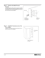
switch (the lowest being U1). Attach the rear railtray brackets to the rear rack uprights at U1. Use one M5 Torx screw for each bracket. HP rack M5 Screw with attached lock washer Rear Tray bracket Step 4: Install the Tinnerman nuts on the front uprights Install the Tinnerman nuts for the - HP Surestore 64 | Installation Guide - Page 4
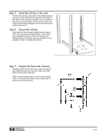
Step 5: Insert the rail tray in the rack Position the rail tray as shown in the following figure and insert it into the rack from the front. The slots in the sides of the rail tray must slide over the posts on the rear rail-tray brackets, and the posts on the rail tray's front mounting flanges must - HP Surestore 64 | Installation Guide - Page 5
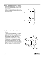
Step 8: Prepare the back rack columns Standing at the back of the rack, count up from the the top of the rail tray (A) to 12th and 28th on the rack's back face. Slide a sheet metal nut (B) on each of the located holes. You should have two sheet metal nuts on each back column face (C). Step 9: - HP Surestore 64 | Installation Guide - Page 6
Step 10: Position the switch on the rails Using a lifting jack, position the switch. Slide the switch back on the rails until the front mounting brackets are against the front rack columns. The use of the Genie Load Lifter is recommended. Step 11: Mount the switch in the rack On one side of the - HP Surestore 64 | Installation Guide - Page 7
Step 12: Install the sliding shelf brackets (Management Station only) Select a U slot above the switch. On each back column of the rack, locate the hole (A) that is 2 holes up from the EIA number of the selected U slot (B). Line up this hole with the threaded hole on the bracket's side. Using a - HP Surestore 64 | Installation Guide - Page 8
At the back of the rack, tighten the screws that attach the shelf rails to the mounting brackets. Recommended Cable Management Perform the following instructions after installating the switch: • Install two cable restraints on each side of the rack (A) in positions that will hold the Fibre Channel - HP Surestore 64 | Installation Guide - Page 9
- HP Surestore 64 | Installation Guide - Page 10
Copyright 2002 Printed in USA 01/02 A6534-96010 *A6534-960010* H
-
 1
1 -
 2
2 -
 3
3 -
 4
4 -
 5
5 -
 6
6 -
 7
7 -
8
-
9
-
10
 |
 |

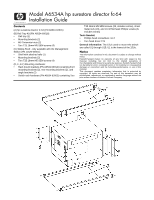
Model A6534A hp surestore director fc-64
Installation Guide
Contents
(A) hp surestore director fc-64 (PN A6534-62001)
(B) Rail Tray Kit (PN A6534-60016):
•
Rail tray (1)
•
Mounting brackets (2)
•
M5 Tinnerman nuts (2)
•
Torx T25 16mm M5 SEM screws (4)
(C) Sliding Shelf - only available with the Management
Station (PN J1526-60001):
•
Shelf with attached rails (1)
•
Mounting brackets (2)
•
Torx T25 16mm M5 SEM screws (4)
(D, E, & F) Mounting Hardware:
•
Rack mount brackets (PN A6534-60014) containing front
mounting brackets (2), rear mounting brackets (2), and
angle brackets (2)
•
Switch rack hardware (PN A6534-62002) containing Torx
T25 16mm M5 SEM screws (22, includes extras), sheet
metal nuts (18), and 10-32 flat-head Phillips screws (8,
includes extras)
Tools Needed:
•
Phillips head screwdriver, no.2
•
Torx head driver T25
General Information:
The 15Us used to mount the switch
are called U1 through U15; U1 is the lowest of the 15Us.
Notice
The information contained in this document is subject to change without
notice.
Hewlett-Packard makes no warranty of any kind with regard to this
material, including, but not limit to, the implied warranties of
merchantability and fitness for a particular purpose. Hewlett-Packard shall
not be liable for errors contained herein or for incidental or consequential
damages in connection with the furnishing performance, or use of this
material.
This document contains proprietary information that is protected by
copyright. All rights are reserved. No part of this document may be
photocopied, reproduced, or translated to another language without the
prior written consent of Hewlett-Packard Company.