HP Tc4400 Maintenance and Service Guide
HP Tc4400 - Compaq Tablet PC Manual
 |
UPC - 883585078639
View all HP Tc4400 manuals
Add to My Manuals
Save this manual to your list of manuals |
HP Tc4400 manual content summary:
- HP Tc4400 | Maintenance and Service Guide - Page 1
HP Compaq tc4400 Tablet PC Document Part Number: 383208-002 May 2006 This guide is a troubleshooting reference used for maintaining and servicing the tablet PC. It provides comprehensive information on identifying tablet PC features, components, and spare parts; troubleshooting tablet PC problems - HP Tc4400 | Maintenance and Service Guide - Page 2
Hewlett-Packard Development Company, L.P. Microsoft and Windows are services. Nothing herein should be construed as constituting an additional warranty. HP shall not be liable for technical or editorial errors or omissions contained herein. Maintenance and Service Guide HP Compaq tc4400 Tablet PC - HP Tc4400 | Maintenance and Service Guide - Page 3
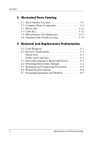
Features 1-2 1.2 Resetting the Tablet PC 1-4 1.3 Power Management 1-5 1.4 External Components 1-6 1.5 Design Overview 1-22 2 Troubleshooting 2.1 Computer Menu 2-4 Selecting from the System Configuration Menu. . . . 2-5 2.2 Troubleshooting Flowcharts 2-6 Maintenance and Service Guide iii - HP Tc4400 | Maintenance and Service Guide - Page 4
(Not Illustrated 3-13 3.6 Sequential Part Number Listing 3-15 4 Removal and Replacement Preliminaries 4.1 Tools Required 4-1 4.2 Service Considerations 4-2 Plastic Parts 4-2 Cables and Connectors 4-2 4.3 Preventing Damage to Removable Drives 4-3 4.4 Preventing Electrostatic Damage - HP Tc4400 | Maintenance and Service Guide - Page 5
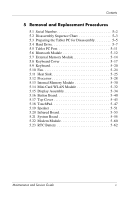
5 Removal and Replacement Procedures 5.1 Serial Number 5-2 5.2 Disassembly Sequence Chart 5-3 5.3 Preparing the Tablet PC for Disassembly 5-5 5.4 Hard Drive 5-7 5.5 Tablet PC Feet 5-11 5.6 Bluetooth Module 5-12 5.7 External Memory Module 5-14 5.8 Keyboard Cover 5-17 5.9 Keyboard 5-20 5.10 - HP Tc4400 | Maintenance and Service Guide - Page 6
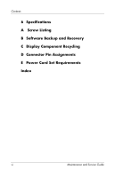
Contents 6 Specifications A Screw Listing B Software Backup and Recovery C Display Component Recycling D Connector Pin Assignments E Power Cord Set Requirements Index vi Maintenance and Service Guide - HP Tc4400 | Maintenance and Service Guide - Page 7
1 Product Description The HP Compaq tc4400 Tablet PC offers advanced modularity, Intel® Core™ Duo and Celeron® M processors, and extensive multimedia support. HP Compaq tc4400 Tablet PC Maintenance and Service Guide 1-1 - HP Tc4400 | Maintenance and Service Guide - Page 8
colors ■ 100-, 80-, or 60-GB high-capacity hard drive, varying by tablet PC model ■ 256-MB DDR2 synchronous DRAM (SDRAM) at 633 MHz and 533 MHz, expandable to 4.0 GB ■ Microsoft® Windows® XP Tablet Edition ■ Full-size Windows keyboard with embedded numeric keypad ■ TouchPad and pointing stick - HP Tc4400 | Maintenance and Service Guide - Page 9
(headphone) ❏ Audio-in (microphone) ❏ Universal Serial Bus (USB) v. 2.0 (3 ports, 1 powered) ❏ Power ❏ External monitor ❏ RJ-45 (network) ❏ RJ-11 (modem) ❏ S-Video-out ❏ PC Card ❏ Digital Media Slot ❏ Primary battery pack ❏ Travel battery pack ❏ Docking connector Maintenance and Service Guide 1-3 - HP Tc4400 | Maintenance and Service Guide - Page 10
battery). 3. Wait approximately 5 minutes. 4. Replace the RTC battery and reassemble the tablet PC. 5. Connect AC power to the tablet PC. Do not reinsert any batteries at this time. 6. Turn on the tablet PC. All passwords and all CMOS settings have been cleared. 1-4 Maintenance and Service Guide - HP Tc4400 | Maintenance and Service Guide - Page 11
Product Description 1.3 Power Management The tablet PC comes with power management features that extend battery pack operating time and conserve power. The tablet PC supports the following power management features: ■ Standby ■ Hibernation ■ Setting customization by the user ■ Hotkeys for setting - HP Tc4400 | Maintenance and Service Guide - Page 12
the tablet PC are shown below and described in Table 1-1. Front Components Item 1 2 Component Wireless light Power light . ■ Blinking rapidly: An HP Smart AC Adapter with a higher power rating should be connected. ■ Off: The computer is off or in hibernation. 1-6 Maintenance and Service Guide - HP Tc4400 | Maintenance and Service Guide - Page 13
parked the hard drive. Infrared port Provides wireless communication between the computer and an optional IrDA-compliant device. Display release button Opens the tablet PC. Fingerprint reader Allows a fingerprint logon to Windows instead of using a password. Maintenance and Service Guide 1-7 - HP Tc4400 | Maintenance and Service Guide - Page 14
Product Description The external components on the right side of the tablet PC are shown below and described in Table 1-2. Right-Side Components 1-8 Maintenance and Service Guide - HP Tc4400 | Maintenance and Service Guide - Page 15
your tablet PC has ■ a PC Card slot, it supports optional Type I, Type II, 32-bit (CardBus), or 16-bit PC Cards. ■ a smart card reader, it accepts smart cards or Java™ Cards. Digital Media Slot Supports Secure Digital (SD) Memory Cards and MultiMediaCards (MMC). Maintenance and Service Guide 1-9 - HP Tc4400 | Maintenance and Service Guide - Page 16
vents. Use the computer only a hard, flat surface. Do not allow a hard surface, such as an adjoining printer, or a soft surface, such as pillows or thick rugs or clothing, to block airflow. ✎ Depending on the tablet PC model, vents vary in number and location. 1-10 Maintenance and Service Guide - HP Tc4400 | Maintenance and Service Guide - Page 17
PC has stopped responding and Microsoft Windows shutdown procedures cannot be used, slide toward the front of the tablet PC and hold for 4 seconds to turn off the tablet PC. Speaker Enables you to listen to music and hear audio alerts and signals from programs. Maintenance and Service Guide - HP Tc4400 | Maintenance and Service Guide - Page 18
Product Description The external components on the rear panel of the tablet PC are shown below and described in Table 1-4. Rear Panel Components 1-12 Maintenance and Service Guide - HP Tc4400 | Maintenance and Service Guide - Page 19
tablet PC using a standard USB cable. RJ-11 (modem) jack Connects a modem cable. Enabled with 56-K connectivity. RJ-45 (network) jack Connects a network cable. Enabled with 10BASE-T/100BASE-TX/1000BASE-T connectivity. Smart adapter power connector Connects an AC adapter, an optional AC adapter - HP Tc4400 | Maintenance and Service Guide - Page 20
Product Description The standard keyboard components of the tablet PC are shown below and described in Table 1-5. Standard Keyboard Components 1-14 Maintenance and Service Guide - HP Tc4400 | Maintenance and Service Guide - Page 21
5 6 7 8 Table 1-5 Standard Keyboard Components Component Function Function keys (6) Perform system and application tasks. When combined with the fn or the esc key. Windows logo key Displays the Microsoft Windows Start menu. Windows applications key Displays a shortcut Service Guide 1-15 - HP Tc4400 | Maintenance and Service Guide - Page 22
Product Description The tablet PC top components are shown below and described in Table 1-6. Top Components 1-16 Maintenance and Service Guide - HP Tc4400 | Maintenance and Service Guide - Page 23
overheating, do not obstruct vents. Use the computer only a hard, flat surface. Do not allow a hard surface, such as an adjoining printer, or a soft surface tablet PC sound. Volume up button Increases tablet PC sound. TouchPad scroll zone Scrolls upward or downward. Maintenance and Service Guide - HP Tc4400 | Maintenance and Service Guide - Page 24
Product Description The tablet PC display components are shown below and described in Table 1-7. Display Components 1-18 Maintenance and Service Guide - HP Tc4400 | Maintenance and Service Guide - Page 25
keyboard. ■ Press inward to enter a command. ■ Rotate upward to scroll upward. ■ Rotate downward to scroll downward. Internal microphone Records sound. Pen eject button Ejects the pen from the pen holder. Pen holder Secures the pen to the tablet PC. Maintenance and Service Guide 1-19 - HP Tc4400 | Maintenance and Service Guide - Page 26
Product Description The external components on the bottom of the tablet PC are shown below and described in Table 1-8. Bottom Components 1-20 Maintenance and Service Guide - HP Tc4400 | Maintenance and Service Guide - Page 27
, to block airflow. Battery bay Holds the battery pack. Battery release latch Releases the battery pack from the battery bay. Hard drive cover Holds the primary hard drive. Expansion memory module compartment Contains one expansion memory module slot. Maintenance and Service Guide 1-21 - HP Tc4400 | Maintenance and Service Guide - Page 28
and features of the tablet PC. Refer to Chapter 3, "Illustrated Parts Catalog," to identify replacement parts, and Chapter 5, "Removal and Replacement Procedures," for disassembly steps. The system board provides the following device connections: ■ Audio ■ Display ■ Hard drive ■ Intel Core Duo and - HP Tc4400 | Maintenance and Service Guide - Page 29
by HP should repair this equipment. All troubleshooting and safety hazard. Any indication of component replacement or printed wiring board modification may This utility includes settings that are not available in Windows. Using Computer Setup Information and settings in Computer Service Guide 2-1 - HP Tc4400 | Maintenance and Service Guide - Page 30
Troubleshooting 2. Select the File, Security, Diagnostics, or System Configuration menu. 3. To close the computer, processor, memory and cache size, and system ROM. ■ View BIOS revision, keyboard controller version, and battery pack serial number information. 2-2 Maintenance and Service Guide - HP Tc4400 | Maintenance and Service Guide - Page 31
support. ■ Automatic DriveLock support. System IDs Establish: ■ Notebook asset tracking number. ■ Notebook ownership tags. Disk Sanitizer Establish fast, optimum, or custom settings for disk sanitizing. *Not applicable to SuperDisk LS-120 drives. Maintenance and Service Guide 2-3 - HP Tc4400 | Maintenance and Service Guide - Page 32
Do This Run a quick comprehensive self test on hard drives in the system that support the test features. Run a quick comprehensive test on system memory on the following categories: ■ Walking 0s ■ Walking 1s ■ High Address line testing ■ Alternate Pattern testing 2-4 Maintenance and Service Guide - HP Tc4400 | Maintenance and Service Guide - Page 33
Fan Always on while on AC Power. ■ Data Execution Prevention. ■ LAN Power save. Enable/disable: ■ Embedded WLAN Device Radio. ■ Embedded Bluetooth Device Radio. ■ LAN/WLAN Switching. ■ Wake on LAN from Off. Enable/disable: ■ USB Port. ■ 1394 Port. ■ CardBus Slot. Maintenance and Service Guide 2-5 - HP Tc4400 | Maintenance and Service Guide - Page 34
"Flowchart 2.5-No Power, Part 4" 2.6 "Flowchart 2.6-No Video, Part 1" 2.7 "Flowchart 2.7-No Video, Part 2" 2.8 "Flowchart 2.8-Nonfunctioning Docking Device (if applicable)" 2.9 "Flowchart 2.9-No Operating System (OS) Loading" 2.10 "Flowchart 2.10-No OS Loading, Hard Drive, Part 1" 2.11 - HP Tc4400 | Maintenance and Service Guide - Page 35
? Y Check LED board, speaker connections. Y Go to "Flowchart 2.6-No Video, Part 1." Go to Y "Flowchart 2.9-No Operating System (OS) Loading." Y Go to "Flowchart 2.15-No Audio, Part 1." N All drives working? N Keyboard/ pointing device working? N Connecting to network or modem? End Go to - HP Tc4400 | Maintenance and Service Guide - Page 36
Troubleshooting Flowchart 2.2-No Power, Part 1 No power (power LED is off). Remove from docking device (if applicable). N Power up on battery power? Y Reset power.* N Power up on battery power? Y Go to "Flowchart 2.3-No Power, Part 2." N Power up on AC power? Y Reset power.* N Power up on - HP Tc4400 | Maintenance and Service Guide - Page 37
debris in battery socket and clean if necessary. Y Power on? Done N Check battery pack by recharging it, moving it to another computer, N Power on? Y Replace power supply (if applicable). N Done Power on? Y Go to "Flowchart 2.4-No Power, Part 3." Done Maintenance and Service Guide 2-9 - HP Tc4400 | Maintenance and Service Guide - Page 38
. Y Power on? N N Power outlet active? Y Replace power cord. Y Power on? N Done Done Try different outlet. External Internal or external AC adapter? Replace external AC adapter. Internal N Go to "Flowchart Power on? 2.5-No Power, Part 4." Y Done Done 2-10 Maintenance and Service Guide - HP Tc4400 | Maintenance and Service Guide - Page 39
Y Replace the following items (if applicable). Check computer operation after each replacement: 1. Internal DC-DC converter* 2. Internal AC adapter 3. Processor board* 4. System board* *NOTE: Replace these items as a set to prevent shorting out among components. Done Maintenance and Service Guide - HP Tc4400 | Maintenance and Service Guide - Page 40
the following one at a time. Test after each replacement. 1. Cable between computer and computer display (if applicable) 2. Display 3. System board N Video OK? Y Try another display. N Internal and external video OK? Y Replace system board. Done Done 2-12 Maintenance and Service Guide - HP Tc4400 | Maintenance and Service Guide - Page 41
, and for monitor connection. Try another external monitor. Y Video OK? N Y Internal Done and external Done video OK? N Adjust external monitor display. Go to "Flowchart 2.8-Nonfunctioning Docking Device (if applicable)." Maintenance and Service Guide 2-13 - HP Tc4400 | Maintenance and Service Guide - Page 42
Troubleshooting Flowchart 2.8-Nonfunctioning Docking Device (if applicable) Nonfunctioning docking device. Reset power cord in docking device and power outlet. Check voltage setting on docking device. Reset monitor cable connector at docking device. Y Docking device operating? N Replace docking - HP Tc4400 | Maintenance and Service Guide - Page 43
Troubleshooting Flowchart 2.9-No Operating System (OS) Loading No OS loading.* Reset power cord in docking device and power outlet. No OS loading from hard drive, go to "Flowchart 2.10-No OS Loading, Hard Drive, Part 1." No OS loading from diskette drive, go to "Flowchart 2.13-No OS Loading, - HP Tc4400 | Maintenance and Service Guide - Page 44
Troubleshooting Flowchart 2.10-No OS Loading, Hard Drive, Part 1 OS not loading from hard drive. Y Nonsystem disk message? N Reseat external hard drive. Y OS loading? N N Boot from CD? Y Check the Setup utility for correct booting order. N Boot from hard drive? Y Done Go to "Flowchart 2.11-No OS - HP Tc4400 | Maintenance and Service Guide - Page 45
Troubleshooting Flowchart 2.11-No OS Loading, Hard Drive, Part 2 Continued from "Flowchart 2.10-No OS Loading, Hard Drive, Part 1." Reseat hard drive. N CD or diskette in 1. Replace hard drive. 2. Replace system Y drive? Y board. Hard drive accessible? Done Remove diskette and reboot. N - HP Tc4400 | Maintenance and Service Guide - Page 46
sectors be fixed? Y Clean virus. Y OS loading from hard drive? N Y Diagnostics on diskette? N Replace hard drive. Run diagnostics and follow recommendations. N Fix bad sectors. Boot from hard drive? Replace hard drive. Y Done Replace hard drive. Done 2-18 Maintenance and Service Guide - HP Tc4400 | Maintenance and Service Guide - Page 47
1. Replace diskette drive. 2. Replace system board. N Y Reset the computer. Refer to OS loading? Done Section 1.2, "Resetting the N Tablet PC," for instructions. Change boot priority using the Setup Utility. Go to "Flowchart 2.17-Nonfunctioning Device." Maintenance and Service Guide 2-19 - HP Tc4400 | Maintenance and Service Guide - Page 48
Y Done Go to "Flowchart 2.17-Nonfunctioning Device." Y Reset the computer. Booting order correct? N Refer to Section 1.2, "Resetting the Tablet PC," for instructions. Go to "Flowchart 2.17-Nonfunctioning Device." Correct boot order using the Setup Utility. 2-20 Maintenance and Service Guide - HP Tc4400 | Maintenance and Service Guide - Page 49
Troubleshooting Flowchart 2.15-No Audio, Part 1 No audio. Y Turn up audio internally or Audio? Done externally. N Y Computer in docking device (if applicable)? N Undock N Internal audio? Y Go to "Flowchart 2.16-No Audio, Part 2." Go to "Flowchart 2.16-No Audio, Part 2." Replace the - HP Tc4400 | Maintenance and Service Guide - Page 50
Troubleshooting Flowchart 2.16-No Audio, Part 2 Continued from "Flowchart 2.15-No Audio, Part 1." N Audio driver in OS configured? Y Reload audio drivers. N Correct drivers for application? Y Load drivers and set configuration in OS. Connect to external speaker. N Replace audio Y board - HP Tc4400 | Maintenance and Service Guide - Page 51
? Y Y Any physical device detected? N Replace hard drive. Replace NIC. If integrated NIC, replace system board. Fix or replace broken item. Go to "Flowchart 2.9-No Operating System (OS) Loading." N Device boots properly? Y Done Replace diskette drive. Done Maintenance and Service Guide 2-23 - HP Tc4400 | Maintenance and Service Guide - Page 52
operating properly. Connect computer to good external keyboard. N External device works? Y Replace system board. Reseat internal keyboard connector (if applicable). N OK? Y Replace internal keyboard or cable. Y Done OK? Done N Replace system board. 2-24 Maintenance and Service Guide - HP Tc4400 | Maintenance and Service Guide - Page 53
. Connect computer to good external pointing device. N External device works? Y Replace system board. Reseat internal pointing device connector (if applicable). N OK? Y Replace internal pointing device or cable. Y Done OK? Done N Replace system board. Maintenance and Service Guide 2-25 - HP Tc4400 | Maintenance and Service Guide - Page 54
line. N Y NIC/modem configured Reload drivers and OK? Done in OS? reconfigure. Y N Disconnect all power from the computer and open. Reseat NIC/modem (if applicable). Replace the NIC/modem (if applicable). Y OK? Done N Replace system board. 2-26 Maintenance and Service Guide - HP Tc4400 | Maintenance and Service Guide - Page 55
illustrated parts breakdown and a reference for spare part numbers. 3.1 Serial Number Location When ordering parts or requesting information, provide the tablet PC serial number and tablet PC model number located on the bottom of the tablet PC. Serial Number Location Maintenance and Service Guide - HP Tc4400 | Maintenance and Service Guide - Page 56
Illustrated Parts Catalog 3.2 Computer Major Components Computer Major Components 3-2 Maintenance and Service Guide - HP Tc4400 | Maintenance and Service Guide - Page 57
Parts: Computer Major Components Item 1 2 3 4 5 6 7 Description 12.1-inch, XGA, TFT display assembly (includes wireless antenna transceivers and cables, microphone, fingerprint reader board, and display cable) Keyboard cover Keyboards cable and bracket) Spare Part Number 419156-001 383558-001 - HP Tc4400 | Maintenance and Service Guide - Page 58
Illustrated Parts Catalog Computer Major Components 3-4 Maintenance and Service Guide - HP Tc4400 | Maintenance and Service Guide - Page 59
Catalog Table 3-1 Spare Parts: Computer Major Components (Continued) Item 8 9 Description Memory modules PC2, 5300 2048-MB 1024 ATMC WLAN card for MOW use 802.11a/b/g ATMC WLAN card for ROW use Spare Part Number 419149-001 419145-001 419151-001 419147-001 419148-001 419144-001 419150-001 419146 - HP Tc4400 | Maintenance and Service Guide - Page 60
Illustrated Parts Catalog Table 3-1 Spare Parts: Computer Major Components (Continued) Item Description 802.11a/b/g ATMC WLAN card for use in Japan Spare Part Number 377408-291 3-6 Maintenance and Service Guide - HP Tc4400 | Maintenance and Service Guide - Page 61
Illustrated Parts Catalog Computer Major Components Maintenance and Service Guide 3-7 - HP Tc4400 | Maintenance and Service Guide - Page 62
: PC Card slot bezel Bluetooth board cover Hard drive cover Memory module compartment cover Not illustrated: Computer feet (5) System board Speaker Modem module (high-speed 56 K, includes modem module cable) RTC battery Base enclosure cover Infrared board (includes infrared board cable) Spare Part - HP Tc4400 | Maintenance and Service Guide - Page 63
Illustrated Parts Catalog Computer Major Components Maintenance and Service Guide 3-9 - HP Tc4400 | Maintenance and Service Guide - Page 64
6-cell battery pack Hard drives (all 5400 rpm; include cover and frame) 100-GB 80-GB 60-GB Bluetooth module (includes Bluetooth module cable) Hard drive cover Spare Part Number 419110-001 419111-001 419124-001 419126-001 419125-001 419117-001 419128-001 3-10 Maintenance and Service Guide - HP Tc4400 | Maintenance and Service Guide - Page 65
3-2 Plastics Kit Spare Part Number Information Item 1 2 3 4 5 6 Description Plastics Kit Includes: Bluetooth module cover PC Card slot bezel Base enclosure cover Hard drive cover Memory module compartment cover Tablet PC feet (5) Spare Part Number 419157-001 Maintenance and Service Guide 3-11 - HP Tc4400 | Maintenance and Service Guide - Page 66
Illustrated Parts Catalog 3.4 Cable Kit Table 3-3 Cable Kit Spare Part Number Information Item 1 2 3 4 Description Cable Kit Includes: Button board cable Modem cable Bluetooth module cable Pointing stick cable Spare Part Number 419118-001 3-12 Maintenance and Service Guide - HP Tc4400 | Maintenance and Service Guide - Page 67
battery 367456-001 External MultiBay II 366143-001 External MultiBay II power cable and stand 366144-001 HP Docking Station 413267-001 HP Docking Station 120 W AC adapter 391174-001 Logo Kit 419132-001 HP Docking Station Miscellaneous Plastics Kit 380089-001 MultiBay 8X DVD-ROM Drive - HP Tc4400 | Maintenance and Service Guide - Page 68
Catalog Table 3-4 Miscellaneous Spare Part Information (Continued) Description Power supply, 65 watt Power cords For use in: Australia Netherlands The People's Republic of China Saudi Arabia Spain Sweden/Finland Spare Part Number 419107-001 350188-011 350188-021 350188-001 350188-081 350188-041 - HP Tc4400 | Maintenance and Service Guide - Page 69
use in Spain Power cord for use in Denmark Power cord for use in Saudi Arabia Power cord for use in Japan Power cord for use in the Netherlands Power cord for use in the People's Republic of China Power cord for use in Sweden/Finland Power cord for use in Israel Maintenance and Service Guide 3-15 - HP Tc4400 | Maintenance and Service Guide - Page 70
External MultiBay II External MultiBay II power cable and stand 8-cell travel battery pack MultiBay 8X DVD-ROM Drive (for use in External MultiBay II and HP Docking Station) MultiBay 24X DVD/CD-RW Combo Drive (for use in External MultiBay II and HP Docking Station) Screw Kit 802.11a/b/g FRLN WLAN - HP Tc4400 | Maintenance and Service Guide - Page 71
001 Description 802.11a/b/g FRLN WLAN Mini Card WLAN module for use in Europe HP Docking Station Miscellaneous Plastics Kit Base enclosure cover Screw Kit Keyboard cover RTC battery HP Docking Station 120-W AC adapter Intel Core Duo T2300 (1.67-GHz) processor (includes thermal paste) Intel Core Duo - HP Tc4400 | Maintenance and Service Guide - Page 72
) Fan Hard drive cover Hinge saddle Display inverter Logo Kit Display bezel (includes fingerprint reader board) Display Bracket Kit Display Cable Kit Display enclosure Display mesh tape Display Rubber Screw Cover Kit Modem module (high-speed 56K, includes modem module cable) PC2, 4200 1024-MB memory - HP Tc4400 | Maintenance and Service Guide - Page 73
module PC2, 4200 2048-MB memory module PC2, 5300 2048-MB memory module PC2, 4200 512-MB memory module PC2, 5300 512-MB memory module Microphone 12.1-inch, XGA, TFT display assembly (includes wireless antenna transceivers and cables, microphone, fingerprint reader board, and display cable) Plastics - HP Tc4400 | Maintenance and Service Guide - Page 74
for use in Thailand Keyboard with pointing stick for use in Japan Keyboard with pointing stick for use in Belgium Keyboard with pointing stick for use in Taiwan Keyboard with pointing stick for use in Korea Keyboard with pointing stick for use in Sweden/Finland 3-20 Maintenance and Service Guide - HP Tc4400 | Maintenance and Service Guide - Page 75
Table 3-5 Sequential Part Number Listing (Continued) Spare Part Number 419171-BB1 419171-DD1 431168-001 Description Keyboard with pointing stick for use in Israel Keyboard with pointing stick for use in Iceland Display Bracket Kit (includes display hinges) Maintenance and Service Guide 3-21 - HP Tc4400 | Maintenance and Service Guide - Page 76
This chapter provides essential information for proper and safe removal and replacement service. 4.1 Tools Required You will need the following tools to complete the removal and replacement procedures: ■ Magnetic screwdriver ■ Phillips P0 screwdriver ■ Torx8 T8 screwdriver ■ Flat-bladed - HP Tc4400 | Maintenance and Service Guide - Page 77
parts. Use care when handling the plastic parts. Apply pressure only at the points designated in the maintenance instructions. Cables and Connectors Ä CAUTION: When servicing the tablet PC or snagged by parts being removed or replaced. Handle flex cables with extreme care; these cables - HP Tc4400 | Maintenance and Service Guide - Page 78
, or loss of information, observe the following precautions: ■ Before removing or inserting a hard drive, shut down the tablet PC. If you are unsure whether the tablet PC is off or in hibernation, turn the tablet PC on, and then shut it down through the operating system. ■ Before removing a diskette - HP Tc4400 | Maintenance and Service Guide - Page 79
Removal and Replacement Preliminaries 4.4 Preventing Electrostatic Damage Many provide some protection, but in many cases, the discharge contains enough power to alter device parameters or melt silicon junctions. A sudden discharge of , reducing its life expectancy. 4-4 Maintenance and Service Guide - HP Tc4400 | Maintenance and Service Guide - Page 80
their containers. ■ Always be properly grounded when touching a sensitive component or assembly. ■ Store reusable electrostatic-sensitive parts from assemblies in protective packaging or nonconductive foam. possible, use an ionizer to dissipate electric charges. Maintenance and Service Guide 4-5 - HP Tc4400 | Maintenance and Service Guide - Page 81
components, parts, and assemblies by the case or PCM laminate. Handle these items only at static-free workstations. ■ Avoid contact with pins, leads, or circuitry. ■ Turn off power and input signals before inserting or removing connectors or test equipment. 4-6 Maintenance and Service Guide - HP Tc4400 | Maintenance and Service Guide - Page 82
Removal and Replacement Preliminaries 4.7 Grounding Equipment and Methods Grounding equipment must include either a wrist one megohm resistance ■ Static-dissipative tables or floor mats with hard ties to the ground ■ Field service kits ■ Static awareness labels ■ Material-handling packages ■ - HP Tc4400 | Maintenance and Service Guide - Page 83
Removal and Replacement Preliminaries Table 4-1 shows how humidity affects the electrostatic voltage levels generated by different activities. Table 4-1 Typical Bags 1,500 V Carbon-loaded plastic Floor mats 7,500 V Metallized laminate Floor mats 5,000 V 4-8 Maintenance and Service Guide - HP Tc4400 | Maintenance and Service Guide - Page 84
when servicing the tablet PC. Make special note of each screw and screw lock size and location during removal and replacement. Refer to Appendix C, "Display Component Recycling," for detailed information on screw and screw lock sizes, locations, and usage. Maintenance and Service Guide 5-1 - HP Tc4400 | Maintenance and Service Guide - Page 85
Removal and Replacement Procedures 5.1 Serial Number Report the tablet PC serial number to HP when requesting information or ordering spare parts. The serial number is located on the bottom of the tablet PC. Serial Number Location 5-2 Maintenance and Service Guide - HP Tc4400 | Maintenance and Service Guide - Page 86
Preparing the Tablet PC for Disassembly Battery pack Hard Drive Tablet PC Feet Bluetooth Module External Memory Module Keyboard Cover Keyboard Fan Heat Sink Processor Internal Memory Module # of Screws Removed 0 2 loosened to remove the hard drive cover 1 loosened to remove the hard drive 4 removed - HP Tc4400 | Maintenance and Service Guide - Page 87
Removal and Replacement Procedures Disassembly Sequence Chart ( tablet PC functionality. Then contact Customer Care. Display Assembly 6 Button Board 1 Top Cover 10 TouchPad 4 Speaker 2 Infrared Board 1 System Board 6 Modem Module 2 RTC Battery 0 5-4 Maintenance and Service Guide - HP Tc4400 | Maintenance and Service Guide - Page 88
: 1. Shut down the tablet PC. If you are unsure whether the tablet PC is off or in hibernation, turn the computer on, and then shut it down through the operating system. 2. Disconnect all external devices connected to the tablet PC. 3. Disconnect the power cord. Maintenance and Service Guide 5-5 - HP Tc4400 | Maintenance and Service Guide - Page 89
Replacement Procedures Battery Pack Spare Part Number Information 6-cell battery pack 419111-001 4. Remove the battery pack by following these steps: a. Turn the tablet PC upside down with the rear panel toward you. b. Slide the battery release latch 1 toward you. (The right side of the battery - HP Tc4400 | Maintenance and Service Guide - Page 90
5.4 Hard Drive Removal and Replacement Procedures Hard Drive Spare Part Number Information Hard drives (all 5400 rpm; include cover, frame, and connector) 100-GB 80-GB 60-GB 419124-001 419126-001 419125-001 1. Prepare the tablet PC for disassembly (Section 5.3). Maintenance and Service Guide - HP Tc4400 | Maintenance and Service Guide - Page 91
the tablet PC. 3. Lift the left side of the hard drive cover and swing it to the right 2 and remove it. ✎ The hard drive cover is available using spare part 419128-001 and is also included in the Plastics Kit, spare part number 419157-001. Removing the Hard Drive Cover 5-8 Maintenance and Service - HP Tc4400 | Maintenance and Service Guide - Page 92
and Replacement Procedures 4. Loosen the Phillips PM2.5×13.0 hard drive retention screw 1. 5. Grasp the mylar tab 2 on the hard drive and slide the hard drive to the right 3 to disconnect it from the system board. 6. Remove the hard drive 4. Removing the Hard Drive Maintenance and Service Guide - HP Tc4400 | Maintenance and Service Guide - Page 93
Remove the four Phillips PM3.0×4.0 screws 1 that secure the hard drive frame to the hard drive. 8. Lift the frame straight up 2 to remove if from the hard drive. Removing the Hard Drive Frame Reverse the above procedure to reassemble and install the hard drive. 5-10 Maintenance and Service Guide - HP Tc4400 | Maintenance and Service Guide - Page 94
Removal and Replacement Procedures 5.5 Tablet PC Feet The tablet PC feet are adhesive-backed rubber pads. The feet are included in the Plastics Kit, spare part number 419157-001. Replacing the Tablet PC Feet Maintenance and Service Guide 5-11 - HP Tc4400 | Maintenance and Service Guide - Page 95
and Replacement Procedures 5.6 Bluetooth Module Bluetooth Module Spare Part Number Information Bluetooth module (includes Bluetooth module cable) 419117-001 1. Prepare the tablet PC for disassembly (Section 5.3). 2. Remove the hard drive cover (Section 5.4). 3. Position the tablet PC with - HP Tc4400 | Maintenance and Service Guide - Page 96
Removal and Replacement Procedures 6. Slide the Bluetooth module out of the tablet PC 1. 7. Disconnect the Bluetooth module cable 2 from the board. Removing the Bluetooth Module Reverse the above procedure to install the Bluetooth module. Maintenance and Service Guide 5-13 - HP Tc4400 | Maintenance and Service Guide - Page 97
and Replacement Procedures 5.7 External Memory Module Memory Module Spare Part Number Information PC2, 5300 2048-MB 1024-MB 512-MB 256-MB 419149-001 419145-001 419151-001 419147-001 PC2, 4200 2048-MB 1024-MB 512-MB 256-MB 419148-001 419144-001 419150-001 419146-001 1. Prepare the tablet PC for - HP Tc4400 | Maintenance and Service Guide - Page 98
tablet PC. 4. Lift the left side of the cover and swing it to the right 2 to remove the memory module compartment cover. ✎ The memory module compartment cover is included in the Plastics Kit, spare part number 419157-001. Removing the Memory Module Compartment Cover Maintenance and Service Guide - HP Tc4400 | Maintenance and Service Guide - Page 99
and Replacement Procedures 5. Spread the retaining tabs 1 on each side of the memory module socket to release the memory module. (The side of the module opposite the socket rises away from the tablet PC.) 6. Slide the module away from the socket at an angle 2. 7. Remove the memory module. ✎ Memory - HP Tc4400 | Maintenance and Service Guide - Page 100
the tablet PC for disassembly (Section 5.3). 2. Position the tablet PC with the front toward you. 3. Remove the two Torx8 T8M2.0×10.0 screws 1 and the two Torx8 T8M2.0×20.0 screws 2 that secure the keyboard cover to the tablet PC. Removing the Keyboard Cover Screws Maintenance and Service Guide - HP Tc4400 | Maintenance and Service Guide - Page 101
and Replacement Procedures 4. Turn the tablet PC right-side up with the front toward you. 5. Open the tablet PC as far as possible. 6. Lift up the front edges of the keyboard cover until the cover disengages from the tablet PC. Releasing the Keyboard Cover 5-18 Maintenance and Service Guide - HP Tc4400 | Maintenance and Service Guide - Page 102
Removal and Replacement Procedures 7. Swing the right edge of the keyboard cover forward until the cover disengages from the tablet PC. Removing the Keyboard Cover Reverse the above procedure to install the keyboard cover. Maintenance and Service Guide 5-19 - HP Tc4400 | Maintenance and Service Guide - Page 103
Removal and Replacement Procedures 5.9 Keyboard Keyboard Spare Part Number Information Belgium Brazil The the tablet PC for disassembly (Section 5.3). 2. Remove the keyboard cover (Section 5.8). 3. Turn the tablet PC upside down with the front toward you. 5-20 Maintenance and Service Guide - HP Tc4400 | Maintenance and Service Guide - Page 104
Removal and Replacement Procedures 4. Remove the following: 1 Three Torx8 T8M2.0×10.0 screws 2 One Torx8 T8M2.0×5.0 screw Removing the Keyboard Screws Maintenance and Service Guide 5-21 - HP Tc4400 | Maintenance and Service Guide - Page 105
Removal and Replacement Procedures 5. Turn the tablet PC right-side up with the front toward you. 6. Open the tablet PC as far as possible. 7. Slide the keyboard back 1 until the pointing stick cable is system board. Disconnecting the Pointing Stick Cable 5-22 Maintenance and Service Guide - HP Tc4400 | Maintenance and Service Guide - Page 106
Removal and Replacement Procedures 9. Lift the rear edge of the keyboard 1 until it disengages from the tablet PC. 10. Slide the keyboard forward 2 until it rests on the palm rest. 11. Release the ZIF connector to which the keyboard cable is connected and disconnect the keyboard cable 3 from the - HP Tc4400 | Maintenance and Service Guide - Page 107
Removal and Replacement Procedures 5.10 Fan Fan Spare Part Number Information Fan 419127-001 1. Prepare the tablet PC for disassembly (Section 5.3). 2. Remove the keyboard cover (Section 5.8). 3. Release the keyboard (Section 5.9). 4. Disconnect the fan cable 1 from the system board. 5. Remove - HP Tc4400 | Maintenance and Service Guide - Page 108
5.11 Heat Sink Removal and Replacement Procedures Heat Sink Spare Part Number Information Heat sink (includes thermal paste) 419161-001 1. Prepare the tablet PC for disassembly (Section 5.3). 2. Remove the keyboard cover (Section 5.8). 3. Release the keyboard (Section 5.9). 4. Remove the fan ( - HP Tc4400 | Maintenance and Service Guide - Page 109
Removal and Replacement Procedures 6. Lift the right side of the heat sink 1 to disengage it from the processor. 7. Slide the heat sink up and to the right to move the heat sink from side to side to detach the heat sink from the processor. Removing the Heat Sink 5-26 Maintenance and Service Guide - HP Tc4400 | Maintenance and Service Guide - Page 110
surfaces of the heat sink 1 and processor 2 each time the heat sink is removed. Thermal paste is included with all heat sink and processor spare part kits. Thermal Paste Locations Reverse the above procedure to install the heat sink. Maintenance and Service Guide 5-27 - HP Tc4400 | Maintenance and Service Guide - Page 111
-001 409971-001 409970-001 409969-001 419159-001 1. Prepare the tablet PC for disassembly (Section 5.3). 2. Remove the keyboard cover (Section 5.8). 3. Release the keyboard (Section 5.9). 4. Remove the fan (Section 5.10). 5. Remove the heat sink (Section 5.11). 5-28 Maintenance and Service Guide - HP Tc4400 | Maintenance and Service Guide - Page 112
Removal and Replacement Procedures 6. Use a flat-bladed screwdriver to turn the processor locking screw one-half turn counterclockwise 1 until you hear a when you install the processor. Removing the Processor Reverse the above procedure to install the processor. Maintenance and Service Guide 5-29 - HP Tc4400 | Maintenance and Service Guide - Page 113
-001 419151-001 419147-001 PC2, 4200 2048-MB 1024-MB 512-MB 256-MB 419148-001 419144-001 419150-001 419146-001 1. Prepare the tablet PC for disassembly (Section 5.3). 2. Remove the keyboard cover (Section 5.8). 3. Release the keyboard (Section 5.9). 5-30 Maintenance and Service Guide - HP Tc4400 | Maintenance and Service Guide - Page 114
and Replacement Procedures 4. Spread the retaining tabs 1 on each side of the memory module socket to release the memory module. (The side of the memory module opposite the socket rises away from the tablet PC.) 5. Slide the memory module away from the socket at an angle 2. 6. Remove the memory - HP Tc4400 | Maintenance and Service Guide - Page 115
Removal and Replacement Procedures 5.14 Mini Card WLAN Module Mini Card WLAN Module Spare Part Number Information 802.11b/g Prepare the tablet PC for disassembly (Section 5.3). 2. Remove the keyboard cover (Section 5.8). 3. Release the keyboard (Section 5.9). 5-32 Maintenance and Service Guide - HP Tc4400 | Maintenance and Service Guide - Page 116
Removal and Replacement Procedures 4. Make note of which antenna cable is attached to which antenna clip on the Mini Card WLAN module prevent incorrect installation. Removing a Mini Card WLAN Module Reverse the above procedure to install a Mini Card WLAN module. Maintenance and Service Guide 5-33 - HP Tc4400 | Maintenance and Service Guide - Page 117
Display Assembly Spare Part Number Information 12.1-inch, XGA, TFT display assembly (includes wireless antenna transceivers and cables, microphone, fingerprint reader board, and display cable) 419156-001 1. Prepare the tablet PC for disassembly (Section 5.3). 2. Remove the keyboard cover (Section - HP Tc4400 | Maintenance and Service Guide - Page 118
Removal and Replacement Procedures 6. Remove the two Torx8 T8M2.0×20.0 screws 1 that secure the base enclosure cover to the tablet PC. 7. Remove the base enclosure cover 1. Removing the Base Enclosure Cover Maintenance and Service Guide 5-35 - HP Tc4400 | Maintenance and Service Guide - Page 119
Removal and Replacement Procedures 8. Disconnect the display cable from the system board. Disconnecting the Display Cable 5-36 Maintenance and Service Guide - HP Tc4400 | Maintenance and Service Guide - Page 120
Removal and Replacement Procedures 9. Turn the tablet PC right-side up with the front toward you. 10. Open the tablet PC as far as possible. 11. Disconnect the wireless antenna cables from the Mini which the cables are routed. Disconnecting the Display Cables Maintenance and Service Guide 5-37 - HP Tc4400 | Maintenance and Service Guide - Page 121
Removal and Replacement Procedures 14. Rotate the display clockwise 90 degrees 1. 15. Remove the two Torx8 T8M2.0×20.0 screws 2 and the two Phillips PM2.0×8.0 screws 3 that secure the display assembly to the tablet PC. Removing the Display Screws 5-38 Maintenance and Service Guide - HP Tc4400 | Maintenance and Service Guide - Page 122
slightly until it disengages from the tablet PC 1. 18. Route the display connector and cable through the opening 2 in the base enclosure. 19. Remove the display assembly. Removing the Display Assembly Reverse the above procedure to install the display assembly. Maintenance and Service Guide 5-39 - HP Tc4400 | Maintenance and Service Guide - Page 123
Number Information Button board (includes button board cable) 419112-001 1. Prepare the computer for disassembly (Section 5.3) and remove the following components: a. Keyboard cover (Section 5.8) b. Keyboard (Section 5.9) c. Display assembly (Section 5.15) 5-40 Maintenance and Service Guide - HP Tc4400 | Maintenance and Service Guide - Page 124
Removal and Replacement Procedures 2. Disconnect the button board cable 1 from the system board. 3. Remove the Phillips PM2.0×4.0 screw 2 that secures the button board to the switch cover. Removing the Button Board Screw Maintenance and Service Guide 5-41 - HP Tc4400 | Maintenance and Service Guide - Page 125
Removal and Replacement Procedures 4. Lift the left side of the button board 1 until it rests at angle. 5. Remove the button board 2. Removing the Button Board Reverse the above procedure to install the button board. 5-42 Maintenance and Service Guide - HP Tc4400 | Maintenance and Service Guide - Page 126
(Section 5.3) and remove the following components: a. Hard drive (Section 5.4) b. Keyboard cover (Section 5.8) c. Keyboard (Section 5.9) d. Button board (Section 5.16) e. Display assembly (Section 5.15) 2. Turn the tablet PC upside down with the front toward you. Maintenance and Service Guide 5-43 - HP Tc4400 | Maintenance and Service Guide - Page 127
Removal and Replacement Procedures 3. Remove the seven Torx8 T8M2.0×10.0 screws that secure the top cover to the base enclosure. Removing the Top Cover Screws, Part 1 5-44 Maintenance and Service Guide - HP Tc4400 | Maintenance and Service Guide - Page 128
the tablet PC right-side up with the front toward you. 5. Disconnect the TouchPad cable 1 from the system board. 6. Remove the two Torx8 T8M2.0×20.0 screws 2 and the Phillips PM2.0×4.0 screw 3 that secure the top cover to the tablet PC. Removing the Top Cover Screws, Part 2 Maintenance and Service - HP Tc4400 | Maintenance and Service Guide - Page 129
Removal and Replacement Procedures 7. Disconnect the TouchPad cable from the system board 1. 8. Lift the rear edge of the top cover 2 until it disengages straight up 3 and remove it. Removing the Top Cover Reverse the above procedure to install the top cover. 5-46 Maintenance and Service Guide - HP Tc4400 | Maintenance and Service Guide - Page 130
Removal and Replacement Procedures TouchPad Spare Part Number Information TouchPad (includes cable and bracket) 419165-001 1. Prepare the tablet PC for disassembly (Section 5.3) and remove the following components: a. Hard drive (Section 5.4) b. Keyboard cover (Section 5.8) c. Keyboard (Section - HP Tc4400 | Maintenance and Service Guide - Page 131
Removal and Replacement Procedures 3. Remove the four Phillips PM2.0×4.0 screws that secure the TouchPad bracket to the top cover. Removing the TouchPad Bracket Screw 5-48 Maintenance and Service Guide - HP Tc4400 | Maintenance and Service Guide - Page 132
Removal and Replacement Procedures 4. Lift the right side of the TouchPad bracket 1 until it rests at an angle. 5. Slide the TouchPad bracket to the right 2 and remove it. Removing the TouchPad Bracket Maintenance and Service Guide 5-49 - HP Tc4400 | Maintenance and Service Guide - Page 133
TouchPad cable is attached and disconnect the TouchPad cable 1. 7. Slide the TouchPad 2 to the right and remove it. 8. If it is necessary to replace the TouchPad cable, disconnect the cable 3 from the TouchPad board. Removing the TouchPad Reverse the above procedure to install the TouchPad. 5-50 - HP Tc4400 | Maintenance and Service Guide - Page 134
the tablet PC for disassembly (Section 5.3) and remove the following components: a. Hard drive (Section 5.4) b. Keyboard cover (Section 5.8) c. Keyboard (Section 5.9) d. Button board (Section 5.16) e. Display assembly (Section 5.15) f. Top cover (Section 5.17) Maintenance and Service Guide 5-51 - HP Tc4400 | Maintenance and Service Guide - Page 135
1 from the system board and route the cable under the infrared board cable 2. 3. Remove the two Torx8 T8M2.0×5.0 screws 3 that secure the speaker to the tablet PC. 4. Remove the speaker 4. Removing the Speaker Reverse the above procedure to install the speaker. 5-52 Maintenance and Service Guide - HP Tc4400 | Maintenance and Service Guide - Page 136
Removal and Replacement Procedures 5.20 Infrared Board Infrared Board Spare Part Number Information Infrared board (includes infrared board cable) 419113-001 1. Prepare the tablet PC for disassembly (Section 5.3) and remove the following components: a. Hard drive (Section 5.4) b. Keyboard cover - HP Tc4400 | Maintenance and Service Guide - Page 137
Removal and Replacement Procedures 2. Release the ZIF connector to which the infrared board cable is connected and disconnect the cable 1 from the system the infrared board 3. Removing the Infrared Board Reverse the above procedure to install the infrared board. 5-54 Maintenance and Service Guide - HP Tc4400 | Maintenance and Service Guide - Page 138
board: ■ Memory modules (Section 5.7 and Section 5.13) ■ Processor (Section 5.12) ■ Mini Card WLAN module (Section 5.14) ■ Modem module (Section 5.22) ■ RTC battery (Section 5.23) 1. Prepare the tablet PC for disassembly (Section 5.3) and remove the following components: a. Hard drive (Section - HP Tc4400 | Maintenance and Service Guide - Page 139
Removal and Replacement Procedures 2. Disconnect the Bluetooth module cable 1 from the system board and remove the cable. 3. Remove the four Torx8 T8M2.0×5.0 screws 1 that secure the system board to the computer. Removing the System Board Screws, Part 1 5-56 Maintenance and Service Guide - HP Tc4400 | Maintenance and Service Guide - Page 140
2 that secures the thermal shield to the tablet PC. 7. Remove the thermal shield 4. ✎ The hinge saddle is available using spare part number 419129-001. The thermal shield is available using spare part number 419162-001. Removing the System Board Screws, Part 2 Maintenance and Service Guide 5-57 - HP Tc4400 | Maintenance and Service Guide - Page 141
the surfaces of the video chip shield 1 and video chip 2 each time the shield is removed. Thermal paste is included with the system board spare part kit. Video Chip Shield and Video Chip Thermal Paste Locations 5-58 Maintenance and Service Guide - HP Tc4400 | Maintenance and Service Guide - Page 142
Replacement Procedures 8. Lift the left side of the system board 1 until the hard drive connector 2 is clear of the base enclosure. 9. Slide the system board to the left 3 to remove it. Removing the System Board Reverse the above procedure to install the system board. Maintenance and Service Guide - HP Tc4400 | Maintenance and Service Guide - Page 143
Replacement Procedures 5.22 Modem Module Modem Module Spare Part Number Information Modem module (high-speed 56 K, includes modem module cable) 419143-001 1. Prepare the tablet PC for disassembly (Section 5.3) and remove the following components: a. Hard drive 5-60 Maintenance and Service Guide - HP Tc4400 | Maintenance and Service Guide - Page 144
Removal and Replacement Procedures 3. Disconnect the modem cable from the two connectors 1 on the system board. 4. Remove the two Phillips PM2.0×4.0 screws 6. Remove the modem board. Removing the Modem Board Reverse the above procedure to install the modem board. Maintenance and Service Guide 5-61 - HP Tc4400 | Maintenance and Service Guide - Page 145
Replacement Procedures 5.23 RTC Battery RTC Battery Spare Part Number Information RTC battery 383265-001 1. Prepare the tablet PC for disassembly (Section 5.3) and remove the following components: a. Hard drive board upside down with the left side toward you. 5-62 Maintenance and Service Guide - HP Tc4400 | Maintenance and Service Guide - Page 146
Removal and Replacement Procedures 3. Remove the RTC battery from the system board socket. Removing the RTC Battery Reverse the above procedure to install the RTC battery. Make sure the RTC battery is installed with the "+" sign facing up. Maintenance and Service Guide 5-63 - HP Tc4400 | Maintenance and Service Guide - Page 147
This chapter provides physical and performance specifications. Table 6-1 Tablet PC Dimensions Metric U.S. Height (front to back) Width Depth 30.2 to 31.5 mm 285 mm 235 mm 1.19 to 1.24 in 11.22 in 9 in Weight 2.04 kg 4.5 lbs Input Power Operating voltage Operating current 18.5 V dc - HP Tc4400 | Maintenance and Service Guide - Page 148
Specifications Table 6-1 Tablet PC (Continued) Relative humidity (noncondensing) Operating sweep rate ✎ Applicable product safety standards specify thermal limits for plastic surfaces. The tablet PC operates well within this range of temperatures. 6-2 Maintenance and Service Guide - HP Tc4400 | Maintenance and Service Guide - Page 149
Character display Total power consumption Viewing angle 20.7 cm 33.1 cm 39.1 cm Up to 16.8 million 150:1 150 nits typical 8.1 in 13.0 in 15.4 in 0.300 × 0.300 mm 1024 × 768 RGB vertical stripe Edge lit 80 × 25 3.5 W +/-65° horizontal, +/-50° vertical typical Maintenance and Service Guide 6-3 - HP Tc4400 | Maintenance and Service Guide - Page 150
to 55°C (41°F to 131°F) ✎ Certain restrictions and exclusions apply. Consult Customer Care for details. *1 GB = 1 billion bytes when referring to hard drive storage capacity. Actual accessible capacity is less. †Actual drive specifications may differ slightly. 6-4 Maintenance and Service Guide - HP Tc4400 | Maintenance and Service Guide - Page 151
Specifications Table 6-4 6-cell, Li-Ion Battery Pack Dimensions Height Width Depth Weight Energy Voltage Amp-hour capacity Watt-hour capacity Temperature Operating Nonoperating 2. to 45°C 0°C to 60°C 0.79 in 3.70 in 5.28 in 0.75 lb 41°F to 113°F 32°F to 140°F Maintenance and Service Guide 6-5 - HP Tc4400 | Maintenance and Service Guide - Page 152
DMA System Function DMA0 Not applicable DMA1* Not applicable DMA2* Not applicable DMA3 Not applicable DMA4 Direct memory access controller DMA5* Available for PC Card DMA6 Not assigned DMA7 Not assigned *PC Card controller can use DMA 1, 2, or 5. 6-6 Maintenance and Service Guide - HP Tc4400 | Maintenance and Service Guide - Page 153
Standard 101-/102-Key or Microsoft Natural Keyboard Cascaded Intel 82801DB/DBM USB2 Enhanced Host Controller-24CD COM1 Conexant AC-Link Audio Intel 82801DB/DBM SMBus Controller-24C3 Data Fax Modem with SmartCP Diskette drive Parallel port System CMOS/real-time clock Microsoft ACPI-compliant system - HP Tc4400 | Maintenance and Service Guide - Page 154
Specifications Table 6-6 System Interrupts (Continued) IRQ11 Intel USB EHCI controller- IRQ14 Primary IDE channel IRQ15 Secondary IDE channel *Default configuration; audio possible configurations are IRQ5, IRQ7, IRQ9, IRQ10, or none. ✎ PC Cards may assert IRQ3, IRQ4, IRQ5, IRQ7, IRQ9, IRQ10 - HP Tc4400 | Maintenance and Service Guide - Page 155
Opti chipset configuration registers Unused 87334 "Super I/O" configuration for CPU Counter/timer registers Unused Keyboard controller Port B Unused Keyboard controller Unused NMI enable/RTC Unused DMA page registers Unused Port A Unused Interrupt controller no. 2 Maintenance and Service Guide 6-9 - HP Tc4400 | Maintenance and Service Guide - Page 156
Specifications Table 6-7 System I/O Addresses reset Unused Unused Secondary fixed disk controller Unused Primary fixed disk controller Unused Joystick (decoded in ESS1688) Unused Entertainment audio Unused Unused Unused Unused Unused Unused Reserved serial port 6-10 Maintenance and Service Guide - HP Tc4400 | Maintenance and Service Guide - Page 157
FM synthesizer-OPL3 Unused VGA Reserved (parallel port/no EPP support) VGA PC Card controller in CPU Unused Internal modem "A" diskette controller Serial port (COM1/default) PCI configuration index register (PCIDIVO-1) PCI configuration data register (PCIDIVO-1) Maintenance and Service Guide 6-11 - HP Tc4400 | Maintenance and Service Guide - Page 158
00FFFFFF 01000000-047FFFFF 04800000-07FFFFFF 08000000-080FFFFF 08200000-FFFEFFFF FFFF0000-FFFFFFFF System Function Base memory Video memory Video BIOS Unused System BIOS Extended memory Super extended memory Unused Video memory (direct access) Unused System BIOS 6-12 Maintenance and Service Guide - HP Tc4400 | Maintenance and Service Guide - Page 159
A Screw Listing This appendix provides specification and reference information for the screws and screw locks used in the tablet PC. All screws and screw locks listed in this appendix are available in the Screw Kit, spare part number 373556-001. Maintenance and Service Guide A-1 - HP Tc4400 | Maintenance and Service Guide - Page 160
mm 4.5 mm Where used: 1 Two screws that secure the hard drive cover to the tablet PC (documented in Section 5.4) 2 Two screws that secure the memory module compartment drive cover to the tablet PC (documented in Section 5.7) Phillips PM2.0×5.0 Screw Locations A-2 Maintenance and Service Guide - HP Tc4400 | Maintenance and Service Guide - Page 161
PM2.0×5.0 Screw (Continued) Head mm Color Qty. Length Thread Width Black 6 5.0 mm 2.0 mm 4.5 mm Where used: 2 screws that secure the Bluetooth cover to the tablet PC (screws are captured on the cover by C-clips; documented in Section 5.6) Phillips PM2.0×5.0 Screw Locations Maintenance and - HP Tc4400 | Maintenance and Service Guide - Page 162
used: 1 One screw that secures the hard drive to the tablet PC (screw is captured on the hard drive frame by a C-clip; documented in Section hard drive frame to the hard drive (documented in Section 5.4) Phillips PM2.5×13.0 and Phillips PM3.0×4.0 Screw Locations A-4 Maintenance and Service Guide - HP Tc4400 | Maintenance and Service Guide - Page 163
Screw Listing Table A-4 Torx8 T8M2.0×10.0 Screw Head mm Color Qty. Length Thread Width Black 12 10.0 mm 2.0 mm 4.5 mm Where used: 2 screws that secure the keyboard cover to the tablet PC (documented in Section 5.8) Torx8 T8M2.0×10.0 Screw Locations Maintenance and Service Guide A-5 - HP Tc4400 | Maintenance and Service Guide - Page 164
Screw Listing Table A-4 Torx8 T8M2.0×10.0 Screw (Continued) Head mm Color Qty. Length Thread Width Black 12 10.0 mm 2.0 mm 4.5 mm Where used: 3 screws that secure the keyboard to the tablet PC (documented in Section 5.9) Torx8 T8M2.0×10.0 Screw Locations A-6 Maintenance and Service Guide - HP Tc4400 | Maintenance and Service Guide - Page 165
A-4 Torx8 T8M2.0×10.0 Screw (Continued) mm Color Qty. Length Thread Black 12 10.0 mm 2.0 mm Where used: 7 screws that secure the top cover to the tablet PC (documented in Section 5.17) Head Width 4.5 mm Torx8 T8M2.0×10.0 Screw Locations Maintenance and Service Guide A-7 - HP Tc4400 | Maintenance and Service Guide - Page 166
Screw Listing Table A-5 Torx8 T8M2.0×20.0 Screw Head mm Color Qty. Length Thread Width Black 8 20.0 mm 2.0 mm 4.5 mm Where used: 2 screws that secure the keyboard cover to the tablet PC (documented in Section 5.8) Torx8 T8M2.0×20.0 Screw Locations A-8 Maintenance and Service Guide - HP Tc4400 | Maintenance and Service Guide - Page 167
.0 Screw (Continued) Head mm Color Qty. Length Thread Width Black 8 20.0 mm 2.0 mm 4.5 mm Where used: 2 screws that secure the base enclosure cover to the tablet PC (documented in Section 5.15) Torx8 T8M2.0×20.0 Screw Locations Maintenance and Service Guide A-9 - HP Tc4400 | Maintenance and Service Guide - Page 168
.0×20.0 Screw (Continued) Head mm Color Qty. Length Thread Width Black 8 20.0 mm 2.0 mm 4.5 mm Where used: 2 screws that secure the display assembly to the tablet PC (documented in Section 5.15) Torx8 T8M2.0×20.0 Screw Locations A-10 Maintenance and Service Guide - HP Tc4400 | Maintenance and Service Guide - Page 169
Table A-5 Torx8 T8M2.0×20.0 Screw (Continued) mm Color Qty. Length Thread Black 8 20.0 mm 2.0 mm Where used: 2 screws that secure the top cover to the tablet PC (documented in Section 5.17) Head Width 4.5 mm Torx8 T8M2.0×20.0 Screw Locations Maintenance and Service Guide A-11 - HP Tc4400 | Maintenance and Service Guide - Page 170
Screw Listing Table A-6 Torx8 T8M2.0×5.0 Screw Head mm Color Qty. Length Thread Width Black 10 5.0 mm 2.0 mm 4.5 mm Where used: One screw that secures the keyboard to the tablet PC (documented in Section 5.9) Torx8 T8M2.0×5.0 Screw Location A-12 Maintenance and Service Guide - HP Tc4400 | Maintenance and Service Guide - Page 171
(Continued) Head mm Color Qty. Length Thread Width Black 10 5.0 mm 2.0 mm 4.5 mm Where used: 2 screws that secure the Mini Card WLAN module to the tablet PC (documented in Section 5.14) Torx8 T8M2.0×5.0 Screw Locations Maintenance and Service Guide A-13 - HP Tc4400 | Maintenance and Service Guide - Page 172
Thread Width Black 10 5.0 mm 2.0 mm 4.5 mm Where used: 1 Two screws that secure the speaker to the tablet PC (documented in Section 5.19) 2 One screw that secures the infrared board to the tablet PC (documented in Section 5.20) Torx8 T8M2.0×5.0 Screw Locations A-14 Maintenance and Service Guide - HP Tc4400 | Maintenance and Service Guide - Page 173
T8M2.0×5.0 Screw (Continued) Head mm Color Qty. Length Thread Width Black 10 5.0 mm 2.0 mm 4.5 mm Where used: 4 screws that secure the system board to the tablet PC (documented in Section 5.21) Torx8 T8M2.0×5.0 Screw Locations Maintenance and Service Guide A-15 - HP Tc4400 | Maintenance and Service Guide - Page 174
Screw Listing Table A-7 Torx8 T8M2.0×8.0 Screw Head mm Color Qty. Length Thread Width Silver 7 8.0 mm 2.0 mm 4.5 mm Where used: 3 screws that secure the fan to the tablet PC (documented in Section 5.10) Torx8 T8M2.0×8.0 Screw Locations A-16 Maintenance and Service Guide - HP Tc4400 | Maintenance and Service Guide - Page 175
A-7 Torx8 T8M2.0×8.0 Screw (Continued) Head mm Color Qty. Length Thread Width Silver 7 8.0 mm 2.0 mm 4.5 mm Where used: 2 screws that secure the display assembly to the tablet PC (documented in Section 5.15) Torx8 T8M2.0×8.0 Screw Locations Maintenance and Service Guide A-17 - HP Tc4400 | Maintenance and Service Guide - Page 176
mm Where used: 1 One screw that secures the system board and hinge saddle to the tablet PC (documented in Section 5.21) 2 One screw that secures the system board and thermal shield to the tablet PC (documented in Section 5.21) Torx8 T8M2.0×8.0 Screw Locations A-18 Maintenance and Service Guide - HP Tc4400 | Maintenance and Service Guide - Page 177
Screw Listing Table A-8 Torx8 T8M2.5×8.0 Screw mm Color Qty. Length Thread Black 4 8.0 mm 2.5 mm Where used: 4 screws that secure the heat sink to the tablet PC (documented in Section 5.11) Head Width 4.0 mm Torx8 T8M2.5×8.0 Screw Locations Maintenance and Service Guide A-19 - HP Tc4400 | Maintenance and Service Guide - Page 178
Width Black 8 4.0 mm 2.0 mm 4.0 mm Where used: 1 One screw that secures the button board to the tablet PC (documented in Section 5.16) 2 One screw that secures the top cover to the tablet PC (documented in Section 5.17) Phillips PM2.0×4.0 Screw Locations A-20 Maintenance and Service Guide - HP Tc4400 | Maintenance and Service Guide - Page 179
Screw Listing Table A-9 PM2.0×4.0 Screw (Continued) Head mm Color Qty. Length Thread Width Black 8 4.0 mm 2.0 mm 4.0 mm Where used: 4 screws that secure the TouchPad bracket to the top cover (documented in Section 5.18) Phillips PM2.0×4.0 Screw Locations Maintenance and Service Guide A-21 - HP Tc4400 | Maintenance and Service Guide - Page 180
Screw Listing Table A-9 PM2.0×4.0 Screw (Continued) Head mm Color Qty. Length Thread Width Black 8 4.0 mm 2.0 mm 4.0 mm Where used: 2 screws that secure the modem module to the system board (documented in Section 5.22) Phillips PM2.0×4.0 Screw Locations A-22 Maintenance and Service Guide - HP Tc4400 | Maintenance and Service Guide - Page 181
B Software Backup and Recovery Backup HP Backup and Recovery Manager provides several ways to back up the system and to recover optimal system functionality. ✎ HP installed drivers, utilities, and applications can be copied to a CD or to a DVD using HP Backup and Recovery Manager. ✎ Formatted DVD±RW - HP Tc4400 | Maintenance and Service Guide - Page 182
up specific files or folders to the hard drive, to an optional external hard drive, or to discs. ✎ This process will take several minutes, depending on the file size and the speed of the computer. To back up specific files or folders: 1. Select Start > All Programs > HP Backup & Recovery > HP Backup - HP Tc4400 | Maintenance and Service Guide - Page 183
, you are saving the full factory image, including the Windows operating system, software applications, and all personal files and folders. ✎ A copy of the entire hard drive image can be stored on another hard drive, on a network drive, or on recovery discs that you create. ✎ This process may take - HP Tc4400 | Maintenance and Service Guide - Page 184
Software Backup and Recovery Backing Up Modifications Made to the System When you back up modifications since your last backup, you are creating system recovery points. This allows you to save a snapshot of your hard drive at a specific point in time. You can then recover back to that point if you - HP Tc4400 | Maintenance and Service Guide - Page 185
docking station (select tablet PC models only), by clicking one of the available options. Click Next to further define the settings. A summary of your system recovery point settings is displayed. 4. Follow the on-screen instructions. Recovery HP Backup and Recovery Manager analyzes the hard drive - HP Tc4400 | Maintenance and Service Guide - Page 186
Software Backup and Recovery ✎ If you do not have a CD or DVD burner, a copy of the entire hard drive image can be stored on another hard drive or on a network drive. ■ Perform a recovery. You can perform a full system recovery or recover important files from the recovery partition on the hard drive - HP Tc4400 | Maintenance and Service Guide - Page 187
a Recovery Performing a Recovery from the Recovery Discs To perform a recovery from the recovery discs: 1. Back up all personal files. 2. Insert the first recovery disc into the optical drive and restart the computer. 3. Follow the on-screen instructions. Maintenance and Service Guide B-7 - HP Tc4400 | Maintenance and Service Guide - Page 188
initiate a recovery from the hard drive recovery partition: 1. Back up all personal files. 2. Restart the computer, and then press f11 before the Windows operating system loads. 3. Click a recovery option, and then click Next. 4. Follow the on-screen instructions. B-8 Maintenance and Service Guide - HP Tc4400 | Maintenance and Service Guide - Page 189
backlight. Careful handling should be exercised when removing these components. ✎ Materials Disposal This HP product contains mercury in the backlight in the display assembly that might require special handling at Industries Alliance (EIA) at http://www.eiae.org. Maintenance and Service Guide C-1 - HP Tc4400 | Maintenance and Service Guide - Page 190
from one display assembly to another. The procedures provided in this appendix are general disassembly instructions. Specific details, such as screw sizes, quantities, and locations, and component shapes and sizes, can vary from one tablet PC model to another. C-2 Maintenance and Service Guide - HP Tc4400 | Maintenance and Service Guide - Page 191
Display Component Recycling Perform the following steps to disassemble the display assembly: 1. Remove all screw covers 1 and screws 2 that secure the display bezel to the display assembly. Removing the Display Bezel Screw Covers and Screws Maintenance and Service Guide C-3 - HP Tc4400 | Maintenance and Service Guide - Page 192
Display Component Recycling 2. Lift up and out on the left and right inside edges 1 and the top and bottom inside edges 2 of the display bezel until the bezel disengages from the display assembly. 3. Remove the display bezel 3. Removing the Display Bezel C-4 Maintenance and Service Guide - HP Tc4400 | Maintenance and Service Guide - Page 193
Display Component Recycling 4. Disconnect all display panel cables 1 from the display inverter and remove the inverter 2. Removing the Display Inverter Maintenance and Service Guide C-5 - HP Tc4400 | Maintenance and Service Guide - Page 194
Display Component Recycling 5. Remove all screws 1 that secure the display panel assembly to the display enclosure. 6. Remove the display panel assembly 2 from the display enclosure. Removing the Display Panel Assembly C-6 Maintenance and Service Guide - HP Tc4400 | Maintenance and Service Guide - Page 195
Display Component Recycling 7. Turn the display panel assembly upside down. 8. Remove all screws that secure the display panel frame to the display panel. Removing the Display Panel Frame Screws Maintenance and Service Guide C-7 - HP Tc4400 | Maintenance and Service Guide - Page 196
Display Component Recycling 9. Use a sharp-edged tool to cut the tape 1 that secures the sides of the display panel to the display panel frame. 10. Remove the display panel frame 2 from the display panel. Removing the Display Frame C-8 Maintenance and Service Guide - HP Tc4400 | Maintenance and Service Guide - Page 197
Display Component Recycling 11. Remove the screws 1 that secure the backlight cover to the display panel. 12. Lift the top edge of the backlight cover 2 and swing it forward. 13. Remove the backlight cover. Removing the Backlight Cover Maintenance and Service Guide C-9 - HP Tc4400 | Maintenance and Service Guide - Page 198
Display Component Recycling 14. Turn the display panel right-side up. 15. Remove the backlight cables 1 from the clip 2 in the display panel. Releasing the Backlight Cables C-10 Maintenance and Service Guide - HP Tc4400 | Maintenance and Service Guide - Page 199
Display Component Recycling 16. Turn the display panel upside down. 17. Remove the backlight frame from the display panel. Removing the Backlight Frame Maintenance and Service Guide C-11 - HP Tc4400 | Maintenance and Service Guide - Page 200
avoid damaging this component and causing exposure to the mercury. 18. Slide the backlight out of the backlight frame. Removing the Backlight C-12 Maintenance and Service Guide - HP Tc4400 | Maintenance and Service Guide - Page 201
3 from the display rear panel. 22. Release the tape 4 that secures the LCD panel to the display rear panel. Releasing the LCD Panel Maintenance and Service Guide C-13 - HP Tc4400 | Maintenance and Service Guide - Page 202
Display Component Recycling 23. Remove the LCD panel. Removing the LCD Panel 24. Recycle the LCD panel and backlight. C-14 Maintenance and Service Guide - HP Tc4400 | Maintenance and Service Guide - Page 203
D Connector Pin Assignments Table D-1 Audio-Out (Headphone) Pin Signal 1 Audio out, left channel 2 Audio out, right channel Pin Signal 3 Ground Maintenance and Service Guide D-1 - HP Tc4400 | Maintenance and Service Guide - Page 204
Connector Pin Assignments Table D-2 Audio-In (Microphone) Pin Signal 1 Audio signal in 2 Audio signal in Pin Signal 3 Ground Table D-3 Universal Serial Bus Pin Signal 1 +5 VDC 2 Data - Pin Signal 3 Data + 4 Ground D-2 Maintenance and Service Guide - HP Tc4400 | Maintenance and Service Guide - Page 205
analog Pin Signal 9 +5 VDC 10 Ground 11 Monitor detect 12 DDC 2B data 13 Horizontal sync 14 Vertical sync 15 DDC 2B clock Maintenance and Service Guide D-3 - HP Tc4400 | Maintenance and Service Guide - Page 206
Connector Pin Assignments Table D-5 RJ-11 (Modem) Pin Signal 1 Unused 2 Tip 3 Ring Pin Signal 4 Unused 5 Unused 6 Unused D-4 Maintenance and Service Guide - HP Tc4400 | Maintenance and Service Guide - Page 207
Connector Pin Assignments Table D-6 RJ-45 (Network) Pin Signal 1 Transmit + 2 Transmit - 3 Receive + 4 Unused Pin Signal 5 Unused 6 Receive - 7 Unused 8 Unused Maintenance and Service Guide D-5 - HP Tc4400 | Maintenance and Service Guide - Page 208
Connector Pin Assignments Table D-7 S-Video-Out Pin Signal 1 S-VHS color (C) signal 2 Composite video signal 3 S-VHS intensity (Y) signal 4 S-VHS color ground Pin Signal 5 TV-CD 6 S-VHS intensity ground 7 Composite video ground D-6 Maintenance and Service Guide - HP Tc4400 | Maintenance and Service Guide - Page 209
or 220 to 240 volts AC. The power cord set included with the computer meets the requirements for use in the country where the equipment is purchased. Power cord sets for use in other countries must meet the requirements of the country where the computer is used. Maintenance and Service Guide E-1 - HP Tc4400 | Maintenance and Service Guide - Page 210
applicable to all countries. ■ The length of the power cord set must be at least 1.5 m (5.0 ft) and a maximum of 2.0 m (6.5 ft). ■ All power amps and a nominal voltage rating of 125 or 250 V AC, as required by each country's power system. ■ The appliance coupler must meet the mechanical configuration - HP Tc4400 | Maintenance and Service Guide - Page 211
Set Requirements Country-Specific Requirements 3-Conductor Power Cord Set Requirements Country/Region Accredited Agency Applicable Note Number Australia EANSW 1 Austria OVE 1 type with a Japanese Industrial Standard C8303 (7 A, 125 V) configuration. Maintenance and Service Guide E-3 - HP Tc4400 | Maintenance and Service Guide - Page 212
Power Cord Set Requirements (Continued) Country/Region Accredited Agency Applicable , 1.0 mm² conductor size. Power cord set fittings (appliance coupler and 75 mm² conductor size. Power cord set fittings (appliance coupler 0.75 mm² conductor size. Power cord set fittings (appliance coupler - HP Tc4400 | Maintenance and Service Guide - Page 213
A accessory battery connector 1-21 arrow keys 1-15 audio troubleshooting 2-21 audio-in jack location 1-9 pin assignments D-2 audio-out jack location 1-9 pin assignments D-1 B base enclosure cover location 1-21 spare part number 3-8, 3-17 base enclosure, spare part number 3-10, 3-17 battery bay - HP Tc4400 | Maintenance and Service Guide - Page 214
Digital Media Slot 1-9 digitizer components mesh, spare part number 3-18 mylar, spare part number 3-18 spare part number 3-18 disassembly sequence chart 5-3 diskette drive OS loading problems 2-19 precautions 4-3 display assembly removal 5-34 spare part number 3-3, 5-34 specifications 6-3 Display - HP Tc4400 | Maintenance and Service Guide - Page 215
24 spare part number 3-3, 3-18, 5-24 features 1-2 feet illustrated 3-11 locations 5-11 fingerprint reader, location 1-7 flowcharts, troubleshooting no audio 2-21, 2-22 no network/modem connection 2-26 no OS loading 2-15 no OS loading from diskette drive 2-19 no OS loading from hard drive 2-16, 2-17 - HP Tc4400 | Maintenance and Service Guide - Page 216
5-25 hinge saddle removal 5-57 spare part number 3-8, 3-18 HP Docking Station 120-W AC adapter, spare part number 3-17 HP Docking Station Miscellaneous Plastics Kit, spare part number 3-13, 3-17 HP Docking Station, spare part number 3-13, 3-17 I I/O address specifications 6-9 Info Center button 1-11 - HP Tc4400 | Maintenance and Service Guide - Page 217
26 nonfunctioning device, troubleshooting 2-14, 2-23 num lock key 1-15 O optical drive OS loading problems 2-20 precautions 4-3 P packing precautions 4-5 password clearing 1-4 PC Card slot 1-9 PC Card slot bezel, illustrated 3-11 pen eject button 1-19 pen holder 1-19 plastic parts 4-2 Plastics Kit - HP Tc4400 | Maintenance and Service Guide - Page 218
security cable slot 1-10 serial number 3-1, 5-2 service considerations 4-2 smart card reader 1-9 speaker location 1-11 removal 5-51 spare part number 3-8, 3-19, 5-51 specifications battery pack 6-5 display 6-3 hard drive 6-4 I/O addresses 6-9 interrupts 6-7 memory map 6-12 system DMA 6-6 tablet PC - HP Tc4400 | Maintenance and Service Guide - Page 219
port location 1-9, 1-11, 1-13 pin assignments D-2 unknown password 1-4 V vents 1-10, 1-17, 1-21 video troubleshooting 2-12 volume buttons 1-17 W Windows applications key 1-15 Windows logo key 1-15 Windows Security button 1-19 Wireless Antenna Kit, spare part number 3-17 wireless button 1-11 wireless
-
 1
1 -
 2
2 -
 3
3 -
 4
4 -
 5
5 -
 6
6 -
 7
7 -
8
-
9
-
10
-
11
-
12
-
13
-
14
-
15
-
16
-
17
-
18
-
19
-
20
-
21
-
22
-
23
-
24
-
25
-
26
-
27
-
28
-
29
-
30
-
31
-
32
-
33
-
34
-
35
-
36
-
37
-
38
-
39
-
40
-
41
-
42
-
43
-
44
-
45
-
46
-
47
-
48
-
49
-
50
-
51
-
52
-
53
-
54
-
55
-
56
-
57
-
58
-
59
-
60
-
61
-
62
-
63
-
64
-
65
-
66
-
67
-
68
-
69
-
70
-
71
-
72
-
73
-
74
-
75
-
76
-
77
-
78
-
79
-
80
-
81
-
82
-
83
-
84
-
85
-
86
-
87
-
88
-
89
-
90
-
91
-
92
-
93
-
94
-
95
-
96
-
97
-
98
-
99
-
100
-
101
-
102
-
103
-
104
-
105
-
106
-
107
-
108
-
109
-
110
-
111
-
112
-
113
-
114
-
115
-
116
-
117
-
118
-
119
-
120
-
121
-
122
-
123
-
124
-
125
-
126
-
127
-
128
-
129
-
130
-
131
-
132
-
133
-
134
-
135
-
136
-
137
-
138
-
139
-
140
-
141
-
142
-
143
-
144
-
145
-
146
-
147
-
148
-
149
-
150
-
151
-
152
-
153
-
154
-
155
-
156
-
157
-
158
-
159
-
160
-
161
-
162
-
163
-
164
-
165
-
166
-
167
-
168
-
169
-
170
-
171
-
172
-
173
-
174
-
175
-
176
-
177
-
178
-
179
-
180
-
181
-
182
-
183
-
184
-
185
-
186
-
187
-
188
-
189
-
190
-
191
-
192
-
193
-
194
-
195
-
196
-
197
-
198
-
199
-
200
-
201
-
202
-
203
-
204
-
205
-
206
-
207
-
208
-
209
-
210
-
211
-
212
-
213
-
214
-
215
-
216
-
217
-
218
-
219
 |
 |

t
Maintenance and Service
Guide
HP Compaq tc4400 Tablet PC
Document Part Number: 383208-002
May 2006
This guide is a troubleshooting reference used for maintaining
and servicing the tablet PC. It provides comprehensive
information on identifying tablet PC features, components, and
spare parts; troubleshooting tablet PC problems; and performing
tablet PC disassembly procedures.