HP Tc4400 Maintenance and Service Guide - Page 116
the Mini Card WLAN module., away from the socket at an angle
 |
UPC - 883585078639
View all HP Tc4400 manuals
Add to My Manuals
Save this manual to your list of manuals |
Page 116 highlights
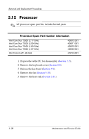
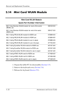
Removal and Replacement Procedures 4. Make note of which antenna cable is attached to which antenna clip on the Mini Card WLAN module, then disconnect the auxiliary and main antenna cables 1 from the Mini Card WLAN module. 5. Remove the two Phillips PM2.0×5.0 screws 2 that secure the Mini Card WLAN module to the computer. (The edge of the Mini Card WLAN module opposite the socket rises away from the computer.) 6. Remove the Mini Card WLAN module by pulling the module away from the socket at an angle 3. ✎ The Mini Card WLAN modules are designed with a notch 4 to prevent incorrect installation. Removing a Mini Card WLAN Module Reverse the above procedure to install a Mini Card WLAN module. Maintenance and Service Guide 5-33
-
 1
1 -
2
-
3
-
4
-
5
-
6
-
7
-
8
-
9
-
10
-
11
-
12
-
13
-
14
-
15
-
16
-
17
-
18
-
19
-
20
-
21
-
22
-
23
-
24
-
25
-
26
-
27
-
28
-
29
-
30
-
31
-
32
-
33
-
34
-
35
-
36
-
37
-
38
-
39
-
40
-
41
-
42
-
43
-
44
-
45
-
46
-
47
-
48
-
49
-
50
-
51
-
52
-
53
-
54
-
55
-
56
-
57
-
58
-
59
-
60
-
61
-
62
-
63
-
64
-
65
-
66
-
67
-
68
-
69
-
70
-
71
-
72
-
73
-
74
-
75
-
76
-
77
-
78
-
79
-
80
-
81
-
82
-
83
-
84
-
85
-
86
-
87
-
88
-
89
-
90
-
91
-
92
-
93
-
94
-
95
-
96
-
97
-
98
-
99
-
100
-
101
-
102
-
103
-
104
-
105
-
106
-
107
-
108
-
109
-
110
-
 111
111 -
 112
112 -
 113
113 -
 114
114 -
 115
115 -
 116
116 -
 117
117 -
 118
118 -
 119
119 -
 120
120 -
 121
121 -
122
-
123
-
124
-
125
-
126
-
127
-
128
-
129
-
130
-
131
-
132
-
133
-
134
-
135
-
136
-
137
-
138
-
139
-
140
-
141
-
142
-
143
-
144
-
145
-
146
-
147
-
148
-
149
-
150
-
151
-
152
-
153
-
154
-
155
-
156
-
157
-
158
-
159
-
160
-
161
-
162
-
163
-
164
-
165
-
166
-
167
-
168
-
169
-
170
-
171
-
172
-
173
-
174
-
175
-
176
-
177
-
178
-
179
-
180
-
181
-
182
-
183
-
184
-
185
-
186
-
187
-
188
-
189
-
190
-
191
-
192
-
193
-
194
-
195
-
196
-
197
-
198
-
199
-
200
-
201
-
202
-
203
-
204
-
205
-
206
-
207
-
208
-
209
-
210
-
211
-
212
-
213
-
214
-
215
-
216
-
217
-
218
-
219
 |
 |
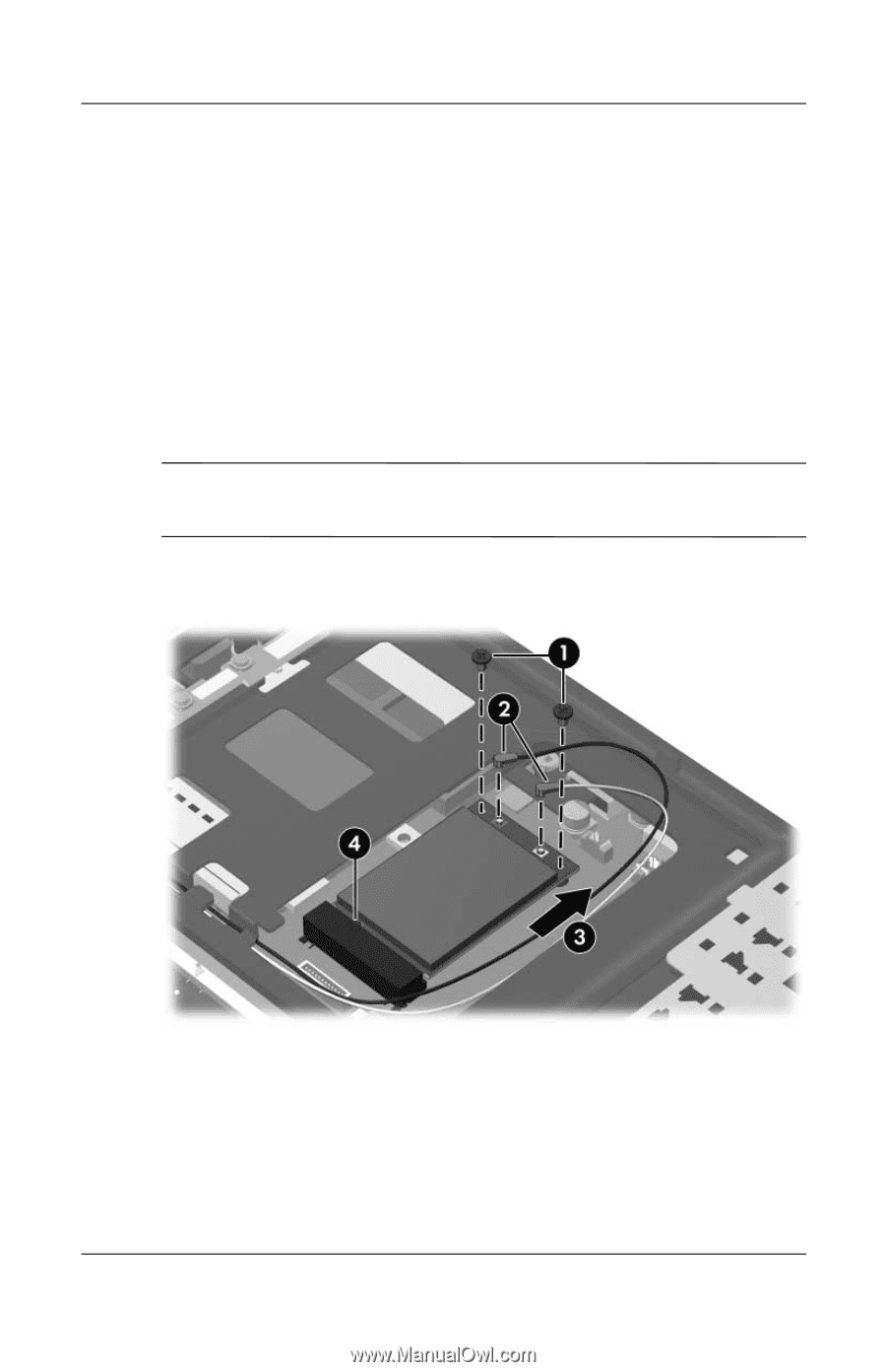
Removal and Replacement Procedures
Maintenance and Service Guide
5–33
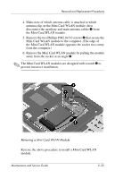
4. Make note of which antenna cable is attached to which
antenna clip on the Mini Card WLAN module, then
disconnect the auxiliary and main antenna cables
1
from
the Mini Card WLAN module.
5.
Remove the two Phillips PM2.0×5.0 screws
2
that secure the
Mini Card WLAN module to the computer. (The edge of
the Mini Card WLAN module opposite the socket rises away
from the computer.)
6.
Remove the Mini Card WLAN module by pulling the module
away from the socket at an angle
3
.
✎
The Mini Card WLAN modules are designed with a notch
4
to
prevent incorrect installation.
Removing a Mini Card WLAN Module
Reverse the above procedure to install a Mini Card WLAN
module.