HP Tc4400 Maintenance and Service Guide - Page 122
Remove the display assembly., Route the display connector and cable through the opening
 |
UPC - 883585078639
View all HP Tc4400 manuals
Add to My Manuals
Save this manual to your list of manuals |
Page 122 highlights
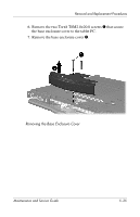
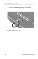
Removal and Replacement Procedures 16. Position the tablet PC with the rear panel toward you. 17. Lift the display assembly slightly until it disengages from the tablet PC 1. 18. Route the display connector and cable through the opening 2 in the base enclosure. 19. Remove the display assembly. Removing the Display Assembly Reverse the above procedure to install the display assembly. Maintenance and Service Guide 5-39
-
 1
1 -
2
-
3
-
4
-
5
-
6
-
7
-
8
-
9
-
10
-
11
-
12
-
13
-
14
-
15
-
16
-
17
-
18
-
19
-
20
-
21
-
22
-
23
-
24
-
25
-
26
-
27
-
28
-
29
-
30
-
31
-
32
-
33
-
34
-
35
-
36
-
37
-
38
-
39
-
40
-
41
-
42
-
43
-
44
-
45
-
46
-
47
-
48
-
49
-
50
-
51
-
52
-
53
-
54
-
55
-
56
-
57
-
58
-
59
-
60
-
61
-
62
-
63
-
64
-
65
-
66
-
67
-
68
-
69
-
70
-
71
-
72
-
73
-
74
-
75
-
76
-
77
-
78
-
79
-
80
-
81
-
82
-
83
-
84
-
85
-
86
-
87
-
88
-
89
-
90
-
91
-
92
-
93
-
94
-
95
-
96
-
97
-
98
-
99
-
100
-
101
-
102
-
103
-
104
-
105
-
106
-
107
-
108
-
109
-
110
-
111
-
112
-
113
-
114
-
115
-
116
-
 117
117 -
 118
118 -
 119
119 -
 120
120 -
 121
121 -
 122
122 -
 123
123 -
 124
124 -
 125
125 -
 126
126 -
 127
127 -
128
-
129
-
130
-
131
-
132
-
133
-
134
-
135
-
136
-
137
-
138
-
139
-
140
-
141
-
142
-
143
-
144
-
145
-
146
-
147
-
148
-
149
-
150
-
151
-
152
-
153
-
154
-
155
-
156
-
157
-
158
-
159
-
160
-
161
-
162
-
163
-
164
-
165
-
166
-
167
-
168
-
169
-
170
-
171
-
172
-
173
-
174
-
175
-
176
-
177
-
178
-
179
-
180
-
181
-
182
-
183
-
184
-
185
-
186
-
187
-
188
-
189
-
190
-
191
-
192
-
193
-
194
-
195
-
196
-
197
-
198
-
199
-
200
-
201
-
202
-
203
-
204
-
205
-
206
-
207
-
208
-
209
-
210
-
211
-
212
-
213
-
214
-
215
-
216
-
217
-
218
-
219
 |
 |

Removal and Replacement Procedures
Maintenance and Service Guide
5–39
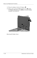
16. Position the tablet PC with the rear panel toward you.
17.
Lift the display assembly slightly until it disengages from the
tablet PC
1
.
18.
Route the display connector and cable through the opening
2
in the base enclosure.
19. Remove the display assembly.
Removing the Display Assembly
Reverse the above procedure to install the display assembly.