HP rp5800 Maintenance & Service Guide HP rp5800 Retail System - Page 85
System Board Drive Connections, CAUTION,
 |
View all HP rp5800 manuals
Add to My Manuals
Save this manual to your list of manuals |
Page 85 highlights
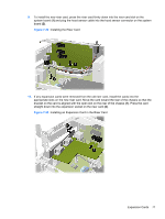
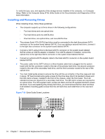
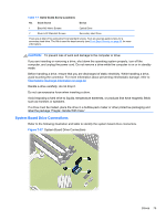
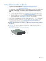
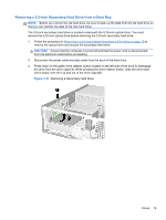
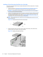
Table 7-7 Extra Guide Screw Locations No. Guide Screw Device 1 Black M3 Metric Screws Optical Drive 2 Silver 6-32 Standard Screws Secondary Hard Drive There are at total of five extra silver 6-32 standard screws. Four are used as guide screws for a secondary hard drive. The fifth is used for bezel security (see Front Bezel Security on page 44 for more information). CAUTION: To prevent loss of work and damage to the computer or drive: If you are inserting or removing a drive, shut down the operating system properly, turn off the computer, and unplug the power cord. Do not remove a drive while the computer is on or in standby mode. Before handling a drive, ensure that you are discharged of static electricity. While handling a drive, avoid touching the connector. For more information about preventing electrostatic damage, refer to Electrostatic Discharge Information on page 34 Handle a drive carefully; do not drop it. Do not use excessive force when inserting a drive. Avoid exposing a hard drive to liquids, temperature extremes, or products that have magnetic fields such as monitors or speakers. If a drive must be mailed, place the drive in a bubble-pack mailer or other protective packaging and label the package "Fragile: Handle With Care." System Board Drive Connections Refer to the following illustration and table to identify the system board drive connectors. Figure 7-37 System Board Drive Connections Drives 75
-
 1
1 -
2
-
3
-
4
-
5
-
6
-
7
-
8
-
9
-
10
-
11
-
12
-
13
-
14
-
15
-
16
-
17
-
18
-
19
-
20
-
21
-
22
-
23
-
24
-
25
-
26
-
27
-
28
-
29
-
30
-
31
-
32
-
33
-
34
-
35
-
36
-
37
-
38
-
39
-
40
-
41
-
42
-
43
-
44
-
45
-
46
-
47
-
48
-
49
-
50
-
51
-
52
-
53
-
54
-
55
-
56
-
57
-
58
-
59
-
60
-
61
-
62
-
63
-
64
-
65
-
66
-
67
-
68
-
69
-
70
-
71
-
72
-
73
-
74
-
75
-
76
-
77
-
78
-
79
-
 80
80 -
 81
81 -
 82
82 -
 83
83 -
 84
84 -
 85
85 -
 86
86 -
 87
87 -
 88
88 -
 89
89 -
 90
90 -
91
-
92
-
93
-
94
-
95
-
96
-
97
-
98
-
99
-
100
-
101
-
102
-
103
-
104
-
105
-
106
-
107
-
108
-
109
-
110
-
111
-
112
-
113
-
114
-
115
-
116
-
117
-
118
-
119
-
120
-
121
-
122
-
123
-
124
-
125
-
126
-
127
-
128
-
129
-
130
-
131
-
132
-
133
-
134
-
135
-
136
-
137
-
138
-
139
-
140
-
141
-
142
-
143
-
144
-
145
-
146
-
147
-
148
-
149
-
150
-
151
-
152
-
153
-
154
-
155
-
156
-
157
-
158
-
159
-
160
-
161
-
162
-
163
-
164
-
165
-
166
-
167
-
168
-
169
-
170
-
171
-
172
-
173
-
174
-
175
-
176
-
177
-
178
-
179
-
180
-
181
-
182
-
183
-
184
-
185
 |
 |
