Hitachi 50V500 Owners Guide - Page 19
The VIDEO OSD label
 |
View all Hitachi 50V500 manuals
Add to My Manuals
Save this manual to your list of manuals |
Page 19 highlights
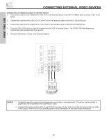
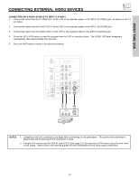
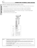
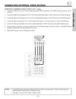
FIRST TIME USE CONNECTING EXTERNAL VIDEO DEVICES CONNECTING A COMPONENT SOURCE TO INPUT 1 OR 2: Y-PBPR. 1. Connect the cable from the Y OUT of the Laserdisc/DVD player or HDTV set top box to the INPUT (Y) jack, as shown on the TV set below. 2. Connect the cable from the CB/PB OUT or B-Y OUT of the Laserdisc/DVD player or HDTV set top box to the INPUT (PB) jack. 3. Connect the cable from the CR/PR OUT or R-Y OUT of the laserdisc/DVD player or HDTV set top box to the INPUT (PR) jack. 4. Connect the cable from the AUDIO OUT R of the Laserdisc/DVD player or HDTV set top box to the INPUT (AUDIO/R) jack. 5. Connect the cable from the AUDIO OUT L of the Laserdisc/DVD player or HDTV set top box to the INPUT (AUDIO/L) jack. 6. Press the VID1 or VID2 button, to view the program from the Laserdisc/DVD player or HDTV set top box. The VIDEO OSD label disappears automatically after approximately four seconds. 7. Press the ANT button to return to the previous channel. DVD Player OUTPUT PR PB Y L R ANT A TO CONVERTER INPUT 1 PR PB DVI-HDTV R (MONO)/L AUDIO ANT B INPUT 2 PR PB Y/VIDEO RR (MONO)/L AUDIO AUDIO TO HI-FI CENTER IN IR BLASTER L R INPUT 3 INPUT 4 MONITOR OUT R (MONO)/L VIDEO R (MONO)/L VIDEO R L VIDEO AUDIO S-VIDEO S-VIDEO S-VIDEO NOTES: 1. Completely insert the connection cord plugs when connecting to rear panel jacks. The picture and sound that is played back will be abnormal if the connection is loose. 2. See page 13 for tips on REAR PANEL CONNECTIONS. 19
-
 1
1 -
2
-
3
-
4
-
5
-
6
-
7
-
8
-
9
-
10
-
11
-
12
-
13
-
 14
14 -
 15
15 -
 16
16 -
 17
17 -
 18
18 -
 19
19 -
 20
20 -
 21
21 -
 22
22 -
 23
23 -
 24
24 -
25
-
26
-
27
-
28
-
29
-
30
-
31
-
32
-
33
-
34
-
35
-
36
-
37
-
38
-
39
-
40
-
41
-
42
-
43
-
44
-
45
-
46
-
47
-
48
-
49
-
50
-
51
-
52
-
53
-
54
-
55
-
56
-
57
-
58
-
59
-
60
-
61
-
62
-
63
-
64
-
65
-
66
-
67
-
68
-
69
-
70
-
71
-
72
-
73
-
74
-
75
-
76
-
77
-
78
-
79
-
80
-
81
-
82
-
83
-
84
 |
 |
