Hitachi B13FI Instruction Manual - Page 15
Operation
 |
UPC - 717709012035
View all Hitachi B13FI manuals
Add to My Manuals
Save this manual to your list of manuals |
Page 15 highlights
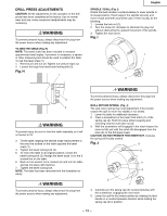
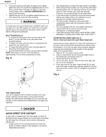
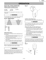
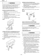
English OPERATION BASIC DRILL PRESS OPERATIONS SPEEDS AND BELT PLACEMENT (Fig. M) This drill press has 5 speeds, as listed below: 680 RPM; 2380 RPM; 1160 RPM; 3000 RPM 1780 RPM; See the inside of the pulley guard for same chart as shown in Figure M. WARNING To avoid possible injury, keep the guard closed, in place, and in proper working order while the tool is in operation. Fig. M - SPEED CHART Spindle 5 4 Motor 5 4 3 3 2 2 1 1 Belt Location RPM 5-5 3000 4-4 2380 3-3 1780 2-2 1160 1-1 680 ON/OFF SWITCH (Fig. N) The keyed switch is intended to prevent unauthorized use of the drill press. 1. To turn the drill press ON (I) insert the yellow key (1) into the key slot in the center of the switch. 2. Push the key firmly into the slot, then push switch to the ON position to start the drill press. 3. To turn the drill press OFF (O) push the switch to the down position. 4. Remove the yellow switch key, when the drill press has come to a complete stop, by gently pulling it outward. WARNING Remove the switch key whenever the drill press is not in use. Place it in a safe place and out of reach of children. Fig. N 1 LASER ON / OFF SWITCH (Fig. L) To turn the laser ON or OFF, press the rocker switch (3) DANGER Laser is radiated when laser guide is turned on. Avoid direct eye exposure. Always un-plug drill press from power source before making any adjustment. INSTALLING A DRILL BIT IN THE CHUCK (Fig. O) 1 With the switch "OFF" and the yellow switch key removed, open the chuck jaws (1) using the chuck key (2). Turn the chuck key counterclockwise to open the chuck jaws (1). 2. Insert the drill bit (3) into the chuck far enough to obtain maximum gripping by the jaws, but not far enough to touch the spiral grooves (flutes) of the drill bit when the jaws are tightened. 3. Make sure that the drill is centered in the chuck. 4. Turn the chuck key clockwise to tighten the jaws. WARNING To avoid injury or accident by the chuck key ejecting forcibly from the chuck when the power is turned ON, use only the self-ejecting chuck key supplied with this drill press. ALWAYS recheck and remove the chuck key before turning the power ON. Fig. O WARNING 2 ALWAYS lock the switch OFF when the drill press is not in 1 use. Remove the key and keep it in a safe place. In the event of power failure, blown fuse, or tripped circuit breaker, turn the switch OFF and remove the key, preventing an accidental 3 startup when power comes on. - 15 -
-
 1
1 -
2
-
3
-
4
-
5
-
6
-
7
-
8
-
9
-
 10
10 -
 11
11 -
 12
12 -
 13
13 -
 14
14 -
 15
15 -
 16
16 -
 17
17 -
 18
18 -
 19
19 -
 20
20 -
21
-
22
-
23
-
24
-
25
-
26
-
27
-
28
-
29
-
30
-
31
-
32
-
33
-
34
-
35
-
36
-
37
-
38
-
39
-
40
-
41
-
42
-
43
-
44
-
45
-
46
-
47
-
48
-
49
-
50
-
51
-
52
-
53
-
54
-
55
-
56
 |
 |
