Hitachi C21-RF80S Service Manual - Page 36
Mechanical Assembly
 |
View all Hitachi C21-RF80S manuals
Add to My Manuals
Save this manual to your list of manuals |
Page 36 highlights
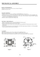
MECHANICAL ASSEMBLY REAR COVER REMOVAL 1.Remove screws from the rear cover as shown in Figure 1. 2.Remove the rear cover. CHASSIS REMOVAL 1.Remove the rear cover (refer to REAR COVER REMOVAL instructions ). 2.Discharge the picture tube anode (2nd anode lead )to the dag coating (picture tube grounding lead). 3.Disconnect the degaussing coil (KE),picture tube socket, deflection yoke connector (KDY),speaker connectors (KL and KR)and 2nd anode lead . 4.Remove chassis completely by sliding it out. PICTURE TUBE REMOVAL 1.Remove the chassis (refer to CHASSIS REMOVAL instructions). 2.Place the front frame face down on a soft surface. 3.Remove the screws on each corner of the picture tube and GENTLY lift the picture tube out of the front frame. 4.Install a replacement picture tube & properly install the degaussing coil and picture tube grounding lead on the picture tube as shown in Figure 2. CAUTION Discharge the picture tube to the coating before handling the tube . Do not adjust the deflection yoke or magnet assembly on the picture tube. Care must be taken to keep these assemblies intact ,unless picture tube is to be replaced. DEGAUSSING COIL DEGAUSSING COIL HOLDER Figure 1 PICTURE TUBE GROUNDING LEAD DEGAUSSING COIL SOCKET To CRT Unit ground Figure 2 -36-
-
 1
1 -
2
-
3
-
4
-
5
-
6
-
7
-
8
-
9
-
10
-
11
-
12
-
13
-
14
-
15
-
16
-
17
-
18
-
19
-
20
-
21
-
22
-
23
-
24
-
25
-
26
-
27
-
28
-
29
-
30
-
 31
31 -
 32
32 -
 33
33 -
 34
34 -
 35
35 -
 36
36 -
 37
37 -
 38
38 -
 39
39 -
 40
40 -
 41
41 -
42
-
43
-
44
-
45
-
46
-
47
-
48
-
49
-
50
-
51
-
52
-
53
-
54
-
55
 |
 |
