Hitachi D10VG Instruction Manual - Page 12
Check the rotational direction Fig. 6 - d10vf
 |
UPC - 717709006157
View all Hitachi D10VG manuals
Add to My Manuals
Save this manual to your list of manuals |
Page 12 highlights
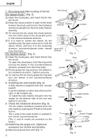
English 7. Mounting and dismounting of the bit For keyed chuck (Fig. 2) (1) Open the chuck jaws, and insert the bit into the chuck. (2) Place the chuck wrench in each of the three holes in the chuck, and turn it in the clockwise direction (viewed from the front side). Tighten securely. (3) To remove the bit, place the chuck wrench into one of the holes in the chuck and turn it in the counterclockwise direction. (4) If it is hard to loosen the sleeve, fix the spindle using the open-end wrench, hold the sleeve firmly, and turn it in the loosening direction (counterclockwise when viewed from the front). For keyless chuck (Fig. 4) (1) Open the chuck jaws, and insert the bit into the chuck. To open the chuck jaws, hold the ring while turning the sleeve in the counterclockwise direction (viewed from the front side). (2) Firmly grasp the ring and turn the sleeve in the clockwise direction. Tighten securely. (3) To remove the bit, firmly grasp the ring and turn the sleeve in the counterclockwise direction. 8. Installing the side handle (Fig. 5) A Side handle is supplied with drill. (except D10VF) It can be installed on either side of the tool for right or left handed use. To install the side handle, thread it into the socket on the desired side of the tool and tighten it securely. 9. Check the rotational direction (Fig. 6) The bit rotates clockwise (viewed from the rear side) by pushing the R-side of the push button. The L-side of the push button is pushed to turn the bit counterclockwise. (The L and R marks are provided on the body.) 10.Attaching the angle unit. (Optional accessory for D13VF and D13VG) (1) Removing chuck from drill (Fig. 7) 12 Drill chuck Chuck Wrench Tighten Loosen Fig. 2 Open End Wrench Loosen Fig. 3 Ring Sleeve Loosen Tighten Fig. 4 Loosen Side Handle Tighten Fig. 5 L mark Siwtch Trigger R mark Fig. 6
-
 1
1 -
2
-
3
-
4
-
5
-
6
-
 7
7 -
 8
8 -
 9
9 -
 10
10 -
 11
11 -
 12
12 -
 13
13 -
 14
14 -
 15
15 -
 16
16 -
 17
17 -
18
-
19
-
20
-
21
-
22
-
23
-
24
-
25
-
26
-
27
-
28
-
29
-
30
-
31
-
32
-
33
-
34
-
35
-
36
-
37
-
38
-
39
-
40
-
41
-
42
-
43
-
44
-
45
-
46
-
47
-
48
-
49
-
50
-
51
-
52
 |
 |
