Honeywell CT54 Owner's Manual - Page 2
Mercury Notice
 |
View all Honeywell CT54 manuals
Add to My Manuals
Save this manual to your list of manuals |
Page 2 highlights
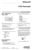
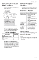
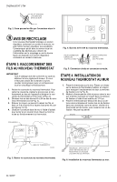
CT54 THERMOSTAT W R L MERCURY NOTICE If this thermostat is replacing a control that contains mercury in a sealed tube, do not place the old thermostat in the trash. Contact your local waste management authority for instructions regarding recycling and proper disposal of this control or of an old control containing mercury in a sealed tube. STEP 3. CONNECT WIRES TO NEW THERMOSTAT IMPORTANT All wiring must comply with local building codes and ordinances. If you are unsure about household wiring procedures, please call your local heating/cooling contractor. 1. Remove the cover on the new thermostat. To remove the cover, insert your thumb into the indentation on the bottom and pull the cover away from the thermostat (see Fig. 3). 2. Loosen the R and W terminal screws on the back of the new thermostat (see Fig. 4). 3. Remove the two wires from the pencil and attach one wire to the R terminal and the other wire to the W terminal (see Fig. 4 and 5). 4. Plug the hole in the wall with insulation to prevent a warm or cool draft from affecting the operation of the thermostat. COVER M19647 Fig. 4. R and W terminals on new thermostat. FOR WRAPAROUND INSERTION STRIP 7/16 IN. (11 MM) FOR STRAIGHT INSERTION STRIP 5/16 IN. (8 MM) M19648 Fig. 5. Wraparound and straight wiring connections. STEP 4. MOUNT NEW THERMOSTAT TO WALL 1. Position the thermostat on the wall. Place a level on top of the thermostat and use a pencil to mark the two mounting holes on the wall (see Fig. 6). 2. Move the thermostat to the side and drill the mounting holes in the wall using a 1/16 in. drill bit at the locations you marked. 3. Position the thermostat over the drilled holes and loosely insert the mounting screws into the drilled holes. Check the leveling of the thermostat and tighten the mounting screws. Do not over tighten. LEVEL BOTTOM OF THERMOSTAT M19646 Fig. 3. Remove cover on new thermostat. DATE CODE MODEL NO. R .18 .2 .9 .7 .5 O .25 N GE .3 .4 MOUNTING HOLE MOUNTING HOLE NOTE: MOVE TEMPERATURE LEVER IF IT BLOCKS MOUNTING HOLE M19649 Fig. 6. Mount new thermostat to wall. 69-1696EF 2
-
 1
1 -
 2
2 -
 3
3 -
 4
4 -
 5
5 -
 6
6 -
 7
7 -
 8
8
 |
 |
