Hotpoint HDA3500NWW Installation Instructions - Page 8
Dishwasher Installation, IMPORTANT - ge
 |
UPC - 084691156185
View all Hotpoint HDA3500NWW manuals
Add to My Manuals
Save this manual to your list of manuals |
Page 8 highlights
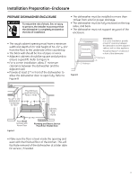
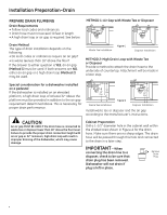
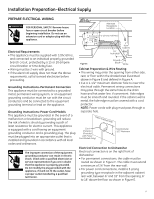
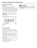
Dishwasher Installation STEP 5: INSTALL POWER CORD Skip this step if the dishwasher will be permanently connected to the house electrical system or has a factory installed power cord. In this step you will need the junction box cover and the #10 x 1/2" hex head screw from the screw kit set aside in Step 1. STEP 6: INSTALL 90° ELBOW • Wrap a 90° elbow with thread seal tape. • Thead the 90° elbow into the water valve. • Do not over tighten the elbow; water valve bracket could bend or the valve fitting could break. • Position the end of the elbow to face the rear of the dishwasher. The power cord and connections must comply with the National Electrical Code, Section 422 and/ or local codes and ordinances. Maximum power cord length is 6 feet. Power Cord Kit WX09X70910, available for purchase from an authorized GE Appliance Dealer, meets these requirements. 90° Elbow Figure K Thread Seal Tape Water Valve Bracket Fill Hose Junction Box Bracket Ground White Black STEP 7: INSTALL DRAIN HOSE TO DISHWASHER DRAIN PORT Skip this step if drain hose has been pre-installed. In this step you will need the drain hose and clamp set aside in Step 1. IMPORTANT - Prevent drain hose damage and possible leaks. Be careful not to nick or cut the drain hose. Figure J • Install strNTahoirtneea:rdCeehldeiecTkfhrTiunhSatmthHaeallrjHnueonslesciLtneioBarndascbAkoeretx bracket. • Insert the power cord through the strain relief and tighten. • Make sure black, white, and green dishwasher wires are threaded throu0g6hFt1h8e4s7mJall hole in the junction box bracket. • Connect power cord white (or ribbed) to dishwasher white, black (or smooth) to dishwasher black and ground to dishwasher green wire. Use UL listed wire nuts of appropriate size. • Install junction box cover using the #10 hex head screw. Be sure wires are not pinched under the cover. 8 • Route t0h6He-s19m49aElllbeonwdInostfatllhe drain hose from the left side of the dishwasher through the strain relief attached to the dishwasher frame and toward the center of the dishwasher as shown in Figures L and M. • Place the hose clamp over the small end of the drain hose. • Push the small end of the drain hose over the drain port on the collection chamber making sure it is fully seated against the hose stop. • Tighten the hose clamp to at least 15 inch-pounds of torque. Note: The drain hose supplied with the dishwasher Strain Relief Figure L Drain Hose
-
 1
1 -
2
-
 3
3 -
 4
4 -
 5
5 -
 6
6 -
 7
7 -
 8
8 -
 9
9 -
 10
10 -
 11
11 -
 12
12 -
 13
13 -
14
-
15
-
16
 |
 |
