Hunter 21117 Owner's Manual - Page 7
Power, White, Black, Common, Light
 |
View all Hunter 21117 manuals
Add to My Manuals
Save this manual to your list of manuals |
Page 7 highlights
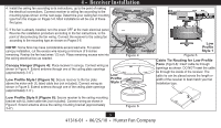
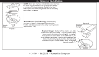
4 • Receiver Installation 6.Use the 2 large (orange) wire connectors supplied to connect the receiver and house wiring, then use the 3 small (blue) wire connectors supplied to connect the receiver and ceiling fan wiring. Refer to the Wiring Diagram in Figure 9. 7.Be sure the antenna is positioned securely, so it can not interfere with the ceiling fan motor. Refer to Figure 9. Do not modify or damage the antenna wire, as control performance may be reduced. After securing the receiver, antenna, and wiring, finish hanging the ceiling fan according to its instructions. Figure 9 Antenna Red Black White Black/Hot (marked "LIVE IN on red label) White/Neutral (marked "COMMON IN" on red label AC Power In Light Fan Common 7 41316-01 • 06/25/10 • Hunter Fan Company
-
 1
1 -
 2
2 -
 3
3 -
 4
4 -
 5
5 -
 6
6 -
 7
7 -
 8
8 -
 9
9 -
 10
10 -
 11
11
 |
 |
