IBM 655743N Service Manual
IBM 655743N - P 92 - 19" CRT Display Manual
 |
UPC - 087944378259
View all IBM 655743N manuals
Add to My Manuals
Save this manual to your list of manuals |
IBM 655743N manual content summary:
- IBM 655743N | Service Manual - Page 1
6557-03N/03S/43N/43S SERVICE MANUAL 6557-03N/43N N. Hemisphere Model AEP Model Japan Model 6557-03S/43S S. Hemisphere Model N3 CHASSIS Picture tube Viewable image size Resolution Standard image area - IBM 655743N | Service Manual - Page 2
only) After correcting the original service problem, perform the following safety checks instructions to use these instruments. 2. A battery-operated AC milliammeter. The Data Precision 245 digital multimeter is suitable for this job SHOWN IN THIS MANUAL OR IN SUPPLEMENTS PUBLISHED BY SONY. - IBM 655743N | Service Manual - Page 3
the power-saving guidelines set by VESA and Energy Star, as well as the more stringent NUTEK . If the monitor is connected to a computer or video graphics board that is VESA DPMS (Display Power Management Signaling) compliant, the monitor will automatically reduce power consumption in three stages - IBM 655743N | Service Manual - Page 4
6557-03N/03S/43N/43S TIMING SPECIFICATION MODE AT PRODUCTION MODE 1 RESOLUTION 656 X 496 CLOCK 25.175 MHz - HORIZONTAL - H-FREQ 31.469 kHz usec H. TOTAL 31.778 H. BLK 5.72 H. FP 0.318 H. SYNC 3.813 H. BP 1.589 H. ACTIV 26.058 - VERTICAL - V. FREQ(HZ) 59.940 Hz lines V. - IBM 655743N | Service Manual - Page 5
2. DISASSEMBLY 2-1. Cabinet Removal 2-1 2-2. A Board Removal 2-1 2-3. AC inI/O TERMINAL Board Removal 2-2 2-4. D Board Removal 2-2 2-5. Service Position 2-3 2-6. H Boards Removal 2-3 2-7. Picture Tube Removal 2-4 3. SAFETY RELATED ADJUSTMENT 3-1 4. ADJUSTMENTS 4-1 5. DIAGRAMS 5-1. Block - IBM 655743N | Service Manual - Page 6
mentioned here are partial abstracts from the Operating Instruction Manual. The page numbers of the Operating Instruction Manual remain as in the manual. SECTION 1 GENERAL Getting sSttaarrtteedd Precautions Installation • Prevent internal heat build-up by allowing adequate air circulation - IBM 655743N | Service Manual - Page 7
9. ** Display Data Channel (DDC) Standard by VESA Note If you use a computer or video board of high output level (about 1.0 Vp-p), you may not be button again. The OPTION OSD appears. EN OPTION ON ZZ... 1 MIN UNLOCK MANUAL DEGAUSS F ES C 4 Press the ¨./> buttons to select " (INPUT)." OPTION - IBM 655743N | Service Manual - Page 8
If you restart the computer you want to view, or that computer is in power saving mode, the monitor may automatically select the other connector's signal. This is because the monitor switches from the interrupted signal to the constant signal. If this happens, manually select the desired signal - IBM 655743N | Service Manual - Page 9
Customizing Your Monitor Using the SIZE On-screen Display The SIZE settings allow you to adjust the size of the picture. Once the setting is adjusted, it will be stored in memory for the current input signal. 1 Press the button. The MENU OSD appears. 2 Press the ¨./> and >?// buttons to select " - IBM 655743N | Service Manual - Page 10
1-5 Customizing Your Monitor Using the COLOR On-screen Display You can change the monitor's color temperature. For example, you can adjust or change the colors of a picture on the screen to match the actual colors of the printed picture. Once the setting is adjusted, it will be stored in memory - IBM 655743N | Service Manual - Page 11
appears. 2 Press the ¨./> and >?// buttons to select " OPTION," and press the button again. The OPTION OSD appears. OPTION ON ZZ... 1 MIN UNLOCK MANUAL DEGAUSS 3 Press the ¨./> buttons to select " ZZ... (PWR SAVE DELAY)." OPTION 1 5 SEC 1 MIN ZZ... 60 MIN OFF PWR SAVE DELAY 4 Press the - IBM 655743N | Service Manual - Page 12
the power-saving guidelines set by VESA and Energy Star, as well as the more stringent NUTEK . If the monitor is connected to a computer or video graphics board that is VESA DPMS (Display Power Management Signaling) compliant, the monitor will automatically reduce power consumption in three stages - IBM 655743N | Service Manual - Page 13
problems, see "Troubleshooting" below. Troubleshooting This section may help you isolate the cause of a problem and as a result, eliminate the need to contact technical support kHz, Vertical: 50 - 160 Hz) Refer to your computer's instruction manual to adjust the video frequency range. • If you are - IBM 655743N | Service Manual - Page 14
with a self-diagnosis function. If there is a problem with your monitor or computer(s), the screen will go blank and the u indicator will number of seconds between orange flashes of the u indicator and inform your service representative of the monitor's condition. Be sure to note the model name - IBM 655743N | Service Manual - Page 15
2-1. CABINET REMOVAL SECTION 2 DISASSEMBLY 5 Seven screws (+BVTT 3 x 8) 3 Four screws (+ BVTP 4 x 16) 1 Two screw covers 4 Cabinet 6557-03N/03S/43N/43S 6 EMI shield 9 Screw (+BVTT 3 x 8) 10 Video shield 7 Four screws (+BVTT 3 x 8) 8 Side cover 2 Two screw covers 2-2. A BOARD REMOVAL CN404 - IBM 655743N | Service Manual - Page 16
6557-03N/03S/43N/43S 2-3. AC INLET AND I/O TERMINAL BOARD REMOVAL CN601 Connector (9pin) 2-4. D BOARD REMOVAL 8 I/O terminal board 2 Two screws (Ext tooth washer screw M4) GND GND CN404 CN403 3 Rear shield CN406 CN405 GND 1 A board 7 Three screws (+BVTT 3 x 8) 6 AC inlet (3P) 4 Screw (Ext - IBM 655743N | Service Manual - Page 17
2-5. SERVICE POSITION 6557-03N/03S/43N/43S AC inlet (3P) CN601 D board 2-6. H BOARD REMOVAL 1 Four screws (Tapping screw 5) Claw CN801 4 H board 3 Two screws (+ BVTAP 3 x 12) 2 Bezel 2-3 - IBM 655743N | Service Manual - Page 18
6557-03N/03S/43N/43S 2-7. PICTURE TUBE REMOVAL 2 Three connectors CN2 (DY) GND (DY) CN4 (DY) 1 Anode cap 4 Two screws (+ BVTT 4 x 8) 3 A board 6 Neck assy 7 Deflection yoke 5 Picture tube • REMOVAL OF ANODE-CAP NOTE: Short circuit the anode of the picture tube and the anode cap to the metal - IBM 655743N | Service Manual - Page 19
SECTION 3 SAFETY RELATED ADJUSTMENT 6557-03N/03S/43N/43S When replacing or repairing the shown below table, the following operational checks must be performed as a safety precaution against X-rays emissions from the unit. HV ADJ Part Replaced ([) RV901 Part Replaced (]) HV Regulator Circuit D - IBM 655743N | Service Manual - Page 20
6557-03N/03S/43N/43S SECTION 4 ADJUSTMENTS • Landing Rough Adjustment 1. Enter the full white signal. (or the full black dots signal). 2. Adjust the contrast to the maximum. 3. Make the screen monogreen. Note: Off the outputs from R ch and B ch of SG. 4. Reverse the DY, and adjust coarsely the - IBM 655743N | Service Manual - Page 21
6557-03N/03S/43N/43S Connect the communication cable of the computer to the connector located on the D board on the monitor. Run the service software and then follow the instruction. IBM AT Computer as a Jig 1 1-690-391-21 2 A-1500-819-A Interface Unit 3 3-702-691-01 Connector Attachment To BUS - IBM 655743N | Service Manual - Page 22
6557-03N/03S/43N/43S MEMO 4-3 - IBM 655743N | Service Manual - Page 23
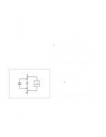
SECTION 5 DIAGRAMS 5-1. BLOCK DIAGRAMS (with FRAME SCHEMATIC DIAGRAM) AC INLET CN601 AC L 1 AC N 3 SW601 F601 POWER 6.3A T601 SWITCH TH601 DGC CN602 THP601 RY601 DGC 4 DGC 1 RY602 RELAY DRIVE Q601 RELAY DRIVE Q607 D601 Q608,609 VCC SW Q602 SW Q610 D(POWER SUPPLY,U-COM,DEFLECTION) - IBM 655743N | Service Manual - Page 24
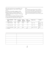
(1) Schematic Diagram of D Board • D BOARD VOLTAGE LIST Ref. Pin No. Voltage [V] Ref. Pin No. Voltage [V] Ref. Pin No. Voltage [V] IC002 5 6 7 IC004 5 6 7 IC005 1 3 7 8 IC009 1 2 3 4 5 6 14 IC010 1 3 4 5 6 7 9 10 12 14 15 16 17 18 19 20 23 24 25 26 27 28 IC012 5 6 7 IC013 1 2 3 4 8 9 10 11 IC501 - IBM 655743N | Service Manual - Page 25
- D BOARD (Conductor Side) - D POWER SUPPLY, U-COM, DEFLECTION - D BOARD (Component Side) - 1 2 3 4 5 1 2 3 4 5 A A B B C C D D E E F F G 5-9 G 5-10 - IBM 655743N | Service Manual - Page 26
- A BOARD (Conductor Side) - A VIDEO AMP RGB OUT • A BOARD SEMICONDUCTOR LOCATION - A BOARD (Component Side) - 1 A B 2 3@ IC ( ) ( ) Conductor Component Side Side 1 IC401 D-1 IC402 D-2 IC403 C-1 C-2 IC404 C-1 IC405 A-2 IC406 A-2 A-1 IC407 B-1 B-2 IC408 D-3 A TRANSISTOR - IBM 655743N | Service Manual - Page 27
(2) Schematic Diagram of A Board CONNECTOR PANEL 54321 10 9 8 7 6 15 14 13 12 11 TO D BOARD CN502 HD15 B.GND2 7 BLUE2 6 NC 5 G.GND2 4 GREEN2 3 R.GND2 2 RED2 1 CN403 7P WHT-L :S-MICRO CN404 6P WHT-L :S-MICRO B.GND1 6 BLUE1 5 G.GND1 4 GREEN1 3 R.GND1 2 RED1 1 TO D BOARD CN502 13W3 - IBM 655743N | Service Manual - Page 28
H USER CONTROL (3) Schematic Diagram of H Board Q803 2SC3311A LED DRIVE STBY+5V Q802 2SC3311A LED DRIVE R809 1k R812 330 R811 220 R810 1k D806 SPB-26MVWF POWER R808 5.6k S807 RESET R807 1k S806 ASC R806 1k R805 680 S804 BRT- R804 470 S803 BRT+ C800 47 25V CN801 10P :XA R803 470 - IBM 655743N | Service Manual - Page 29
5-4. SEMICONDUCTORS BA05T NJM78M09FA TA78M12S LA6500-FA BA9756FS-E2 M62352GP-75E M62352GP-75ED 1 5 LA6510 1 10 LA7841L CAX2043Q 48 37 1 36 12 25 13 24 TOP VIEW CXA2044M LSC4380DW2EL LM1283N DM-57N 18 10 1 9 TOP VIEW FA4111 LM324M MC74HC02AF SN74HC02ANS SN74HC04ANS - IBM 655743N | Service Manual - Page 30
2SC5022-02 2SJ449 2SJ449(1) D1NL20U-TR D1NL40-TA CATHODE BCE ANODE 2SC5301-CC B CE 2SDS1802-S B C E D1NS4 EGP10GPKG23 ERA38-06 RD11ES-B1 RD12ES-B2 RD13ES-B2 RD16ES-B2 RD16ES-B3 RD22ES-B2 RD24ES-B2 RE24ES-B3 RD3.3ES-B2 RD5.1ES-B2 RD6.2ES-B2 RD6.8ES-B1 RD6.8ES-B3 1SS119-25TD 1SS119-25 CATHODE - IBM 655743N | Service Manual - Page 31
SECTION 6 EXPLODED VIEWS 6557-03N/03S/43N/43S • Items with no part number and no description are not stocked because they are seldom required for routine service. • The construction parts of an assembled part are indicated with a collation number in the remark column. • Items marked " * " are not - IBM 655743N | Service Manual - Page 32
6557-03N/03S/43N/43S 6-2. PICTURE TUBE p 7-685-663-71 +BVTP 4X16 π 7-685-881-09 +BVTT 4X8 Les composants identifiés per un tramé et une marque ¡ sont critiques pour la sécurité. Ne les remplacer que par une piéce portant le numéro spécifié. The components identified by shading and mark ¡ are - IBM 655743N | Service Manual - Page 33
CONNECTOR) [43N/43S] REF.NO. PART NO. DESCRIPTION REMARK 107 4-063-796-01 INFORMATION DISK (IBM) 108 ¡ 1-783-507-11 CORD SET, POWER (10A/125V) [43N NH model] 108 ¡ ] 109 3-862-445-01 MANUAL, INSTRUCTION [03N/43N Japan model] 109 3-862-445-11 MANUAL, INSTRUCTION [except 03N/43N Japan model] 6-3 - IBM 655743N | Service Manual - Page 34
. The coRmEpMoAnRenKts idReEnFti.fNieOd. byPA[ RinT NthOis. manual have been carefully factoryselected for each set in order nonflammable REMARK • Items marked " * " are not stocked since they are seldom required for routine service. Some delay should be anticipated when ordering these items. - IBM 655743N | Service Manual - Page 35
The components identified by shading and mark ¡ are critical for safety. Replace only with part number specified. Les composants identifiés per un tramé et une marque ¡ sont critiques pour la sécurité. Ne les remplacer que par une piéce portant le numéro spécifié. 6557-03N/03S/43N/43S A REF.NO. - IBM 655743N | Service Manual - Page 36
6557-03N/03S/43N/43S A REF.NO. PART NO. DESCRIPTION R101 1-215-395-00 METAL 82 R103 1-216-049-91 RES,CHIP 1K R104 1-216-121-91 RES,CHIP 1M R105 1-216-017-91 RES,CHIP 47 R106 1-216-009-00 RES,CHIP 22 R107 R108 R109 R110 R111 1-216-129-00 RES,CHIP 1-219-497-11 CARBON 1-216-039 - IBM 655743N | Service Manual - Page 37
The components identified by shading and mark ¡ are critical for safety. Replace only with part number specified. Les composants identifiés per un tramé et une marque ¡ sont critiques pour la sécurité. Ne les remplacer que par une piéce portant le numéro spécifié. 6557-03N/03S/43N/43S AD REF.NO. - IBM 655743N | Service Manual - Page 38
6557-03N/03S/43N/43S D Les composants identifiés per un tramé et une marque ¡ sont critiques pour la sécurité. Ne les remplacer que par une piéce portant le numéro spécifié. The components identified by shading and mark ¡ are critical for safety. Replace only with part number specified. REF.NO. - IBM 655743N | Service Manual - Page 39
The components identified by shading and mark ¡ are critical for safety. Replace only with part number specified. Les composants identifiés per un tramé et une marque ¡ sont critiques pour la sécurité. Ne les remplacer que par une piéce portant le numéro spécifié. 6557-03N/03S/43N/43S D REF.NO. - IBM 655743N | Service Manual - Page 40
6557-03N/03S/43N/43S D Les composants identifiés per un tramé et une marque ¡ sont critiques pour la sécurité. Ne les remplacer que par une piéce portant le numéro spécifié. The components identified by shading and mark ¡ are critical for safety. Replace only with part number specified. REF.NO. - IBM 655743N | Service Manual - Page 41
The components identified by shading and mark ¡ are critical for safety. Replace only with part number specified. Les composants identifiés per un tramé et une marque ¡ sont critiques pour la sécurité. Ne les remplacer que par une piéce portant le numéro spécifié. 6557-03N/03S/43N/43S D REF.NO. - IBM 655743N | Service Manual - Page 42
6557-03N/03S/43N/43S D REF.NO. PART NO. DESCRIPTION R054 1-216-089-91 RES,CHIP 47K R055 1-216-089-91 RES,CHIP 47K R056 1-216-017-91 RES,CHIP 47 R057 1-216-025-91 RES,CHIP 100 R058 1-216-049-91 RES,CHIP 1K R059 1-216-295-91 SHORT 0 R060 1-216-025-91 RES,CHIP 100 R061 1-216-073-00 RES, - IBM 655743N | Service Manual - Page 43
The components identified by shading and mark ¡ are critical for safety. Replace only with part number specified. Les composants identifiés per un tramé et une marque ¡ sont critiques pour la sécurité. Ne les remplacer que par une piéce portant le numéro spécifié. 6557-03N/03S/43N/43S D REF.NO. - IBM 655743N | Service Manual - Page 44
6557-03N/03S/43N/43S D REF.NO. PART NO. DESCRIPTION R940 1-216-073-00 RES,CHIP 10K R941 1-216-025-91 RES,CHIP R942 1-219-748-11 CARBON R943 1-216-073-00 RES,CHIP R1003 1-216-093-00 RES,CHIP R1004 1-216-667-11 METAL CHIP 100 4.7K 10K 68K 4.7K R1005 1-216-667-11 METAL CHIP R1008 1-216-049-91 RES - IBM 655743N | Service Manual - Page 45
The components identified by shading and mark ¡ are critical for safety. Replace only with part number specified. Les composants identifiés per un tramé et une marque ¡ sont critiques pour la sécurité. Ne les remplacer que par une piéce portant le numéro spécifié. 6557-03N/03S/43N/43S DH REF.NO. - IBM 655743N | Service Manual - Page 46
6557-03N/03S/43N/43S REF.NO. PART NO. DESCRIPTION Les composants identifiés per un tramé et une marque ¡ sont critiques pour la sécurité. Ne les remplacer que par une piéce portant le numéro spécifié. The components identified by shading and mark ¡ are critical for safety. Replace only with part
-
 1
1 -
 2
2 -
 3
3 -
 4
4 -
 5
5 -
 6
6 -
 7
7 -
8
-
9
-
10
-
11
-
12
-
13
-
14
-
15
-
16
-
17
-
18
-
19
-
20
-
21
-
22
-
23
-
24
-
25
-
26
-
27
-
28
-
29
-
30
-
31
-
32
-
33
-
34
-
35
-
36
-
37
-
38
-
39
-
40
-
41
-
42
-
43
-
44
-
45
-
46
 |
 |
CHASSIS
SERVICE MANUAL
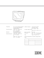
SPECIFICATIONS
6557-03N/03S/43N/43S
N3
COLOR
MONITOR
6557-03N/43N
N. Hemisphere Model
AEP Model
Japan Model
6557-03S/43S
S. Hemisphere Model
Picture tube
0.25 – 0.27 mm aperture grille pitch
19 inches measured diagonally
90-degree deflection
Viewable image size
Approx. 365
×
273 mm (w/h)
(14
3
/
8
×
10
3
/
4
inches)
18.0” viewing image
Resolution
Horizontal: Max. 1600 dots
Vertical: Max. 1200 lines
Standard image area
Approx. 330
×
264 mm (w/h)
(13
×
10
1
/
2
inches)
or
Approx. 352
×
264 mm (w/h)
(13
7
/
8
×
10
1
/
2
inches)
Deflection frequency
Horizontal: 30 to 94 kHz
Vertical: 50 to 160 Hz
256
<
Total Line
<
2048
AC input voltage/current
100 to 240 V, 50 – 60 Hz, 1.8 – 1.0
A
Power consumption
Max. 130 W
Dimensions
462.2
×
477.5
×
475.5 mm (w/h/d)
(18
1
/
4
×
18
7
/
8
×
18
3
/
4
inches)
Mass
Approx. 25 kg (55 lb 2 oz)
Design and specifications are subject to change without
notice.
MODEL
SPEC.
BODY COLOR
DEST.
6557-03N
WHITE TYPE
NH, AEP, J
6557-03S
SH
6557-43N
BLACK TYPE
NH, AEP, J
6557-43S
SH