IBM 8835 Hardware Maintenance Manual
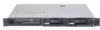
IBM 8835 - Eserver 325 - 1 GB RAM Manual
 |
UPC - 000435158314
View all IBM 8835 manuals
Add to My Manuals
Save this manual to your list of manuals |
IBM 8835 manual content summary:
- IBM 8835 | Hardware Maintenance Manual - Page 1
ERserver 325 Type 8835 Eserver Hardware Maintenance Manual and Troubleshooting Guide - IBM 8835 | Hardware Maintenance Manual - Page 2
- IBM 8835 | Hardware Maintenance Manual - Page 3
ERserver 325 Type 8835 Eserver Hardware Maintenance Manual and Troubleshooting Guide - IBM 8835 | Hardware Maintenance Manual - Page 4
, read Appendix C, "Notices," on page 143. The most recent version of this document is available at http://www.ibm.com/pc/support/. Fifth Edition (November 2004) © Copyright International Business Machines Corporation 2002, 2003. All rights reserved. US Government Users Restricted Rights - Use - IBM 8835 | Hardware Maintenance Manual - Page 5
codes, error messages, and configuration information for the IBM® ™ 325 Type 8835 server. Eserver Important: This manual is intended for trained servicers who are familiar with IBM ® products. Before servicing an IBM product, be sure to Eserver review "Safety information" on page 101. Important - IBM 8835 | Hardware Maintenance Manual - Page 6
iv 325 Type 8835: Hardware Maintenance Manual and Troubleshooting Guide Eserver - IBM 8835 | Hardware Maintenance Manual - Page 7
About this manual iii Important safety information iii Online support iii Chapter firmware update utility program 11 Chapter 3. Diagnostics 13 error messages 16 Text messages 17 Downloading the diagnostics program 17 Starting the the 325 Type 8835 server 26 Eserver Removing the cover - IBM 8835 | Hardware Maintenance Manual - Page 8
listing, Type 8835 93 System 94 Power cord CRUs 96 Appendix A. Getting help and technical assistance 99 Before you call 99 Using the documentation 99 Getting help and information from the World Wide Web 99 vi 325 Type 8835: Hardware Maintenance Manual and Troubleshooting Guide Eserver - IBM 8835 | Hardware Maintenance Manual - Page 9
Software service and support 100 Hardware service and support 100 Appendix B. Related service information 101 Safety information 101 General safety 101 Electrical safety 102 Safety inspection guide 103 Handling electrostatic discharge-sensitive devices 104 Grounding requirements 104 Safety - IBM 8835 | Hardware Maintenance Manual - Page 10
viii 325 Type 8835: Hardware Maintenance Manual and Troubleshooting Guide Eserver - IBM 8835 | Hardware Maintenance Manual - Page 11
General information The IBM 325 Type 8835 server is a 1-U-high1 rack model server for Eserver high-volume network up-to-date information about your server and other IBM server products at http://www.ibm.com/eserver/xseries/. For service, assistance, or information, see Appendix A, "Getting help - IBM 8835 | Hardware Maintenance Manual - Page 12
a problem yourself or to provide helpful information to a service technician. In addition to this Hardware Maintenance Manual and Troubleshooting Guide, the following 325 documentation is provided with your server: Eserver v Installation Guide This printed publication contains instructions for - IBM 8835 | Hardware Maintenance Manual - Page 13
specifications of your 325 Type 8835 server. Depending on your server model, some features Eserver might not be available, adapters (bus 3) v One half-length adapter slot supports up to 100 MHz/64-bit PCI-X adapters (bus 3) v Supports 3.3 V or universal adapters only Acoustical noise emissions: - IBM 8835 | Hardware Maintenance Manual - Page 14
the electrical outlet. Power-control button: Press this button to turn the server on and off manually. Reset button: Press this button to reset the server and run the power-on self-test LED Systemerror LED 4 325 Type 8835: Hardware Maintenance Manual and Troubleshooting Guide Eserver - IBM 8835 | Hardware Maintenance Manual - Page 15
numerous other servers. If your server supports IBM Director, you can use IBM Director to light this LED remotely. keyboard or mouse to this server, you must use a USB keyboard or a USB mouse. After installing a USB keyboard firmware update utility program" on page 11). v You need to create update - IBM 8835 | Hardware Maintenance Manual - Page 16
not run, and all core logic except for the service processor is shut down; however, the server can respond to requests from the service processor, such as a remote request to turn automatically when power is restored. 6 325 Type 8835: Hardware Maintenance Manual and Troubleshooting Guide Eserver - IBM 8835 | Hardware Maintenance Manual - Page 17
connected to ac power, the server can respond to requests from the service processor, such as a remote request to turn on the server. To can turn off the server from the operating system, if your operating system supports this feature. After an orderly shutdown of the operating system, the server - IBM 8835 | Hardware Maintenance Manual - Page 18
v The integrated system management processor can turn off the server as an automatic response to a critical system failure. v You can turn off the server through a request from the service processor. 8 325 Type 8835: Hardware Maintenance Manual and Troubleshooting Guide Eserver - IBM 8835 | Hardware Maintenance Manual - Page 19
firmware update utility program" on page 11. v RAID configuration programs - LSI on these programs, see the User's Guide for this server. IBM intends to make IBM Director and the Remote Supervisor Adapter II v Enable USB keyboard and mouse support (default) © Copyright IBM Corp. 2002, 2003 9 - IBM 8835 | Hardware Maintenance Manual - Page 20
Wake on LAN features that appear on the configuration menu, your server must contain Wake on LAN hardware and software and your operating system must support Wake on LAN functions. 10 325 Type 8835: Hardware Maintenance Manual and Troubleshooting Guide Eserver - IBM 8835 | Hardware Maintenance Manual - Page 21
does not affect any device drivers. Note: To ensure proper server operation, be sure to update the server baseboard management controller firmware code first before updating the BIOS code. For additional information, see the User's Guide on the IBM Eserver Documentation CD. Complete the following - IBM 8835 | Hardware Maintenance Manual - Page 22
12 325 Type 8835: Hardware Maintenance Manual and Troubleshooting Guide Eserver - IBM 8835 | Hardware Maintenance Manual - Page 23
Chapter 3. Diagnostics This chapter provides basic troubleshooting information to help you solve some common problems that might occur with the server. If you cannot locate and correct the problem using the information in this chapter, see Appendix A, "Getting help and technical assistance," on page - IBM 8835 | Hardware Maintenance Manual - Page 24
16. 9. Check for the following responses: a. One beep b. Readable instructions or the main menu 003 DID YOU RECEIVE BOTH OF THE CORRECT RESPONSES? still suspect a problem, see "Undetermined problems" on page 91. 14 325 Type 8835: Hardware Maintenance Manual and Troubleshooting Guide Eserver - IBM 8835 | Hardware Maintenance Manual - Page 25
beep codes and messages to indicate successful test completion or the detection of a problem. See "Power-on self-test" for more information. v Diagnostic programs The diagnostic programs are stored on the IBM Enhanced Diagnostics CD. These programs are the primary method of testing the major - IBM 8835 | Hardware Maintenance Manual - Page 26
the check digits that are used to verify the validity of the information. text message is the diagnostic message that indicates the reason for the problem. 16 325 Type 8835: Hardware Maintenance Manual and Troubleshooting Guide Eserver - IBM 8835 | Hardware Maintenance Manual - Page 27
that is used to analyze the problem. Downloading the diagnostics program Complete the following steps to download the latest image of the IBM Enhanced Diagnostics and create a startable Enhanced Diagnostics diskette: 1. Go to http://www.ibm.com/pc/support/. 2. Download the diagnostics file for the - IBM 8835 | Hardware Maintenance Manual - Page 28
instructions on the screen. 5. When the tests have completed, you can view the Test Log by selecting Utility from the top of the screen. You can save the test log to a file on a diskette or to your hard disk drive. 18 325 Type 8835: Hardware Maintenance Manual and Troubleshooting Guide Eserver - IBM 8835 | Hardware Maintenance Manual - Page 29
, make sure that the server has the latest level of BIOS code installed. Error charts You can use the error charts to find solutions to problems that have definite symptoms (see "Error symptoms" on page 78). Important: If diagnostic error messages are displayed that are not listed, make sure that - IBM 8835 | Hardware Maintenance Manual - Page 30
LED (DLED10) Fan 3 error LED (DLED6) Fan 2 error LED (DLED4) Fan 1 error LED (DLED2) Fan 4 error LED (DLED8) Microprocessor 2 error LED (DLED14) 20 325 Type 8835: Hardware Maintenance Manual and Troubleshooting Guide Eserver - IBM 8835 | Hardware Maintenance Manual - Page 31
the server might not restart (reboot) correctly. If this happens, you will need an IBM eServer 325 System BIOS Crisis Recovery Diskette. You can download a file to create this diskette from http://www.ibm.com/pc/support. You will need an external diskette drive to create the diskette. When you have - IBM 8835 | Hardware Maintenance Manual - Page 32
IBM eServer 325 System BIOS Crisis Recovery Diskette into external USB floppy diskette drive A. 8. Replace the cover (see "Removing the cover and bezel" on page 27). 9. Connect the server to a power source, keyboard : 22 325 Type 8835: Hardware Maintenance Manual and Troubleshooting Guide Eserver - IBM 8835 | Hardware Maintenance Manual - Page 33
v If a supervisor password has been set and is known, type the supervisor password at the password prompt (see the User's Guide for more information about passwords). Start the Configuration/Setup Utility program and reset the user password. v Remove the server battery and then reinstall it (see " - IBM 8835 | Hardware Maintenance Manual - Page 34
configuration, replace FRUs of minimal configuration one at a time until the problem is isolated. To use this method, you must know the minimum configuration that is required for the server to start (see page 91). 24 325 Type 8835: Hardware Maintenance Manual and Troubleshooting Guide Eserver - IBM 8835 | Hardware Maintenance Manual - Page 35
Phillips screwdriver available. v For a list of supported options for your server, go to http://www.ibm.com/pc/us/compat/. System reliability guidelines To help that comes with the rack. v You have followed the cabling instructions that come with optional adapters. v You have replaced a failed fan - IBM 8835 | Hardware Maintenance Manual - Page 36
Major components of the 325 Type 8835 server Eserver The blue color on components and labels indicates touch points, where a component can be fans CD-ROM drive assembly USB option tray Hard disk drive 26 325 Type 8835: Hardware Maintenance Manual and Troubleshooting Guide Eserver - IBM 8835 | Hardware Maintenance Manual - Page 37
Removing the cover and bezel Complete the following steps to remove the cover and bezel (with the server out of the rack): 1. Read "Safety information" on page 101 and "Installation guidelines" on page 25. 2. Turn off the server and all attached peripheral devices. Disconnect all power cords; then, - IBM 8835 | Hardware Maintenance Manual - Page 38
those instructions in addition to the instructions in supported RAID adapters, go to http://www.ibm.com/pc/us/compat/. For details about installing a RAID adapter, see the documentation that comes with the adapter. 28 325 Type 8835: Hardware Maintenance Manual and Troubleshooting Guide Eserver - IBM 8835 | Hardware Maintenance Manual - Page 39
are installing the RAID adapter in PCI-X slot 1. See the documentation that comes with the RAID adapter for any additional cabling instructions. That documentation also provides information about installing the RAID software and configuring the RAID adapter. RAID adapter SCSI cable SCSI backplane - IBM 8835 | Hardware Maintenance Manual - Page 40
v If you plan to install an optional IBM Remote Supervisor Adapter II, install it in PCI-X slot 2. Use the ribbon cable that routing. Remote Supervisor Adapter II Cable Remote Supervisor Adapter II connector (JMGT1) 30 325 Type 8835: Hardware Maintenance Manual and Troubleshooting Guide Eserver - IBM 8835 | Hardware Maintenance Manual - Page 41
Installing an adapter Complete the following steps to install an adapter: 1. Read "Safety information" on page 101 and "Installation guidelines" on page 25. 2. Turn off the server and all attached peripheral devices. Disconnect all power cords; then, disconnect all external signal cables from the - IBM 8835 | Hardware Maintenance Manual - Page 42
module toward the front of the server until the alignment tab is free of the slot on the side of the server. 32 325 Type 8835: Hardware Maintenance Manual and Troubleshooting Guide Eserver - IBM 8835 | Hardware Maintenance Manual - Page 43
. Slide the expansion-slot clip toward the server until it snaps into place to secure the adapter in the adapter slot. 11. Connect any internal cables to the adapter. See the instructions that come with the adapter for details. Attention: Ensure that the cables do not block the flow of air from - IBM 8835 | Hardware Maintenance Manual - Page 44
in the server. Before you install a hard disk drive, review the following information: v The server supports two 25.4-mm (1-inch), slim, 3.5-inch hard disk drives. SCSI models of the server come drive" on page 36. 34 325 Type 8835: Hardware Maintenance Manual and Troubleshooting Guide Eserver - IBM 8835 | Hardware Maintenance Manual - Page 45
Installing a hot-swap hard disk drive Before you install a hot-swap hard disk drive, review the following information: v Inspect the drive tray for any signs of damage. v Ensure that the drive is installed in the tray correctly. v If your server has an optional RAID adapter installed, see the - IBM 8835 | Hardware Maintenance Manual - Page 46
read the following information: v See the documentation that comes with the drive for any cabling instructions. v Route the cable before you install the drive. Do not block the airflow from installation" on page 47. 36 325 Type 8835: Hardware Maintenance Manual and Troubleshooting Guide Eserver - IBM 8835 | Hardware Maintenance Manual - Page 47
dual-microprocessor performance, install DIMMs in slots 1, 2, 5, and 6. The server supports 512 MB and 1 GB DIMMs. See the ServerProven® list at http://www.ibm.com/pc/us/compat/ for a list of memory modules that are supported by the server. The following illustration shows the memory slots on the - IBM 8835 | Hardware Maintenance Manual - Page 48
memory connectors enabled). 6. If you have other options to install, install them now. Otherwise, go to "Completing the installation" on page 47. 38 325 Type 8835: Hardware Maintenance Manual and Troubleshooting Guide Eserver - IBM 8835 | Hardware Maintenance Manual - Page 49
if you need to update the BIOS code. The most current level of BIOS code for the server is available at http://www.ibm.com/pc/support/. For additional information, see the User's Guide on the IBM Documentation CD. Eserver 2. To use SMP, obtain an SMP-capable operating system. For a list of - IBM 8835 | Hardware Maintenance Manual - Page 50
://www.ibm.com/pc/us/compat/ for a list of microprocessors that are supported by the server. The following procedure describes installation of a microprocessor. Microprocessors should be removed only by qualified service 8835: Hardware Maintenance Manual and Troubleshooting Guide Eserver - IBM 8835 | Hardware Maintenance Manual - Page 51
Microprocessor Microprocessor orientation indicator Microprocessorlocking lever Microprocessor socket 6. Close the microprocessor-locking lever to secure the microprocessor. Note: A new microprocessor comes in a kit with a heat sink. Attention: Do not disturb or contaminate the thermal material - IBM 8835 | Hardware Maintenance Manual - Page 52
that the thermal material may have formed a strong bond between the heat U.S. and Canada, call your IBM reseller or IBM marketing representative. Note: After you any special handling and installation instructions that come with the 8835: Hardware Maintenance Manual and Troubleshooting Guide Eserver - IBM 8835 | Hardware Maintenance Manual - Page 53
it snaps into place. 8. Put the PCI adapter shield back into place. 9. Reinstall the server cover, and connect the cables. 10. Turn on the server. 11. Start the Configuration/Setup Utility program and set configuration parameters. v Set the system date and time. Chapter 4. Installing options 43 - IBM 8835 | Hardware Maintenance Manual - Page 54
v Set the power-on password. v Reconfigure the server. See the section about using the Configuration/Setup Utility program in the User's Guide for details. 44 325 Type 8835: Hardware Maintenance Manual and Troubleshooting Guide Eserver - IBM 8835 | Hardware Maintenance Manual - Page 55
Replacing a fan assembly The server comes with five replaceable fans. Complete the following steps to replace the fan assembly. Use this procedure to replace any fan in the server. 1. Read "Safety information" on page 101 and "Installation guidelines" on page 25. 2. Turn off the server and all - IBM 8835 | Hardware Maintenance Manual - Page 56
do not come into contact with the metal fan bracket when installation is complete. 8. Continue with "Completing the installation" on page 47. 46 325 Type 8835: Hardware Maintenance Manual and Troubleshooting Guide Eserver - IBM 8835 | Hardware Maintenance Manual - Page 57
cables; then, connect the power cord. For details, see the Rack Installation Instructions that come with the server. Notes: a. Depending on the options that you Updating the server configuration" on page 48 and the User's Guide on the IBM Eserver Documentation CD. b. If you installed a SCSI drive, - IBM 8835 | Hardware Maintenance Manual - Page 58
the server in the User's Guide on the IBM Eserver Documentation CD. Some options have device drivers that you need to install. See support SMP. For additional information, see the operating-system documentation. 48 325 Type 8835: Hardware Maintenance Manual and Troubleshooting Guide Eserver - IBM 8835 | Hardware Maintenance Manual - Page 59
II to manage the server from a remote location, see the section about setting up the adapter in the IBM Eserver 325 Type 8835 User's Guide and in the Remote Supervisor Adapter User's Guide for information about setting up and configuring the adapter and using the adapter to manage the server - IBM 8835 | Hardware Maintenance Manual - Page 60
50 325 Type 8835: Hardware Maintenance Manual and Troubleshooting Guide Eserver - IBM 8835 | Hardware Maintenance Manual - Page 61
these connectors. The 100BASE-TX and 1000BASE-T Fast Ethernet standards require Category 5 or higher cabling. For more information about the Ethernet controller, see the User's Guide. © Copyright IBM Corp. 2002, 2003 51 - IBM 8835 | Hardware Maintenance Manual - Page 62
this connector to connect a monitor to the server. The connector is dark blue to help you identify it. The following illustration shows a video connector. 5 1 15 11 52 325 Type 8835: Hardware Maintenance Manual and Troubleshooting Guide Eserver - IBM 8835 | Hardware Maintenance Manual - Page 63
describes the removal of server components. Important: The field replaceable unit (FRU) procedures are intended for trained servicers who are familiar with IBM products. See the parts Eserver listing in "System" on page 94 to determine if the component being replaced is a customer replaceable - IBM 8835 | Hardware Maintenance Manual - Page 64
"Installing a microprocessor" on page 39. To reuse the heat sink that was removed in step 3 above, see "Thermal grease" on page 55. 54 325 Type 8835: Hardware Maintenance Manual and Troubleshooting Guide Eserver - IBM 8835 | Hardware Maintenance Manual - Page 65
half of the grease will remain in the syringe. 6. Install the heat sink onto the microprocessor as described in "Installing a microprocessor" on page 39. Chapter 6. Service replaceable units 55 - IBM 8835 | Hardware Maintenance Manual - Page 66
server cover (see "Removing the cover and bezel" on page 27) and take out the air baffle. 4. Remove the power-cord module. 56 325 Type 8835: Hardware Maintenance Manual and Troubleshooting Guide Eserver - IBM 8835 | Hardware Maintenance Manual - Page 67
new power supply, reverse this procedure, making sure that all cables are routed correctly and do not block the air flow from the fan. Chapter 6. Service replaceable units 57 - IBM 8835 | Hardware Maintenance Manual - Page 68
two cables to the rear of the card and slide it under the tabs on the chassis until it is firmly anchored. 58 325 Type 8835: Hardware Maintenance Manual and Troubleshooting Guide Eserver - IBM 8835 | Hardware Maintenance Manual - Page 69
Carefully pull the drive assembly out of the chassis. 10. Remove the retaining wires on the drive assembly. 11. To remove the CD-ROM drive from the media tray, pull gently on the drive and slide it out To replace the CD-ROM drive, reverse the previous steps. Chapter 6. Service replaceable units 59 - IBM 8835 | Hardware Maintenance Manual - Page 70
backplane out of the server. To replace the SCSI backplane, reverse the previous steps, making sure to align the tabs and notches. 60 325 Type 8835: Hardware Maintenance Manual and Troubleshooting Guide Eserver - IBM 8835 | Hardware Maintenance Manual - Page 71
System board 6. Pull up gently on the riser card until it detaches from the server. To replace the riser card, reverse the preceding steps. Chapter 6. Service replaceable units 61 - IBM 8835 | Hardware Maintenance Manual - Page 72
: You can also gently pinch the top of each standoff using needle-nose pliers and then pull the baseboard management controller away. 62 325 Type 8835: Hardware Maintenance Manual and Troubleshooting Guide Eserver - IBM 8835 | Hardware Maintenance Manual - Page 73
: To avoid breaking the retaining clips or damaging the connectors, handle the clips gently. To replace the baseboard management controller, reverse the preceding steps. Chapter 6. Service replaceable units 63 - IBM 8835 | Hardware Maintenance Manual - Page 74
) SCSI backplane power (J12) Front panel signal (J13) System board power (J11 Primary IDE (IDE1) Fan 1 (SFAN1) CD-ROM drive power (J14) 64 325 Type 8835: Hardware Maintenance Manual and Troubleshooting Guide Eserver - IBM 8835 | Hardware Maintenance Manual - Page 75
System-board external connectors The following illustration shows the external input/output connectors on the system board. Ethernet ports (Dual)(JLAN1) USB ports (USB2 and USB1) Video port (JVGA1) Serial port 1 (COM1) Serial port 2 (COM2) Chapter 6. Service replaceable units 65 - IBM 8835 | Hardware Maintenance Manual - Page 76
LED (DLED10) Fan 3 error LED (DLED6) Fan 2 error LED (DLED4) Fan 1 error LED (DLED2) Fan 4 error LED (DLED8) Microprocessor 2 error LED (DLED14) 66 325 Type 8835: Hardware Maintenance Manual and Troubleshooting Guide Eserver - IBM 8835 | Hardware Maintenance Manual - Page 77
) PCI-X slot 2 (PCIX2) Remote Supervisor Adapter II (JMGT1) Battery (BAT1) Microprocessor 2 (U2) Note: The VRMs for the microprocessors are integrated on the system board. Chapter 6. Service replaceable units 67 - IBM 8835 | Hardware Maintenance Manual - Page 78
power (J10) SCSI backplane power (J12) Front panel signal (J13) System board power (J11 Primary IDE (IDE1) CD-ROM drive power (J14) 68 325 Type 8835: Hardware Maintenance Manual and Troubleshooting Guide Eserver - IBM 8835 | Hardware Maintenance Manual - Page 79
flash ROM page-swap jumper, see "Recovering from a POST/BIOS update failure" on page 21. Boot block recovery jumper (JBBF1) Clear CMOS jumper (JBAT1) Chapter 6. Service replaceable units 69 - IBM 8835 | Hardware Maintenance Manual - Page 80
place for reinstallation. 10. Remove the SCSI backplane (see "SCSI backplane" on page 60). 11. Disconnect all cables from the system board. 12. Remove the heat sinks from all the slightly from your hardware. 70 325 Type 8835: Hardware Maintenance Manual and Troubleshooting Guide Eserver - IBM 8835 | Hardware Maintenance Manual - Page 81
. Note: When reassembling the components in the server, be sure to route all cables carefully so that they are not exposed to excessive pressure. Chapter 6. Service replaceable units 71 - IBM 8835 | Hardware Maintenance Manual - Page 82
72 325 Type 8835: Hardware Maintenance Manual and Troubleshooting Guide Eserver - IBM 8835 | Hardware Maintenance Manual - Page 83
decide which FRUs to have available when servicing the computer. Notes: 1. Check the configuration before you replace a FRU. Configuration problems can cause false errors and symptoms. 2. For IBM devices not supported by this index, refer to the manual for that device. 3. Always start with "General - IBM 8835 | Hardware Maintenance Manual - Page 84
service Keyboard controller failed) 1. Keyboard 2. System board 2-2-3 1. Battery (CMOS power failure and checksum checks failed) 2. System board 2-4-1 (Video failed; system believed operable) v System board 74 325 Type 8835: Hardware Maintenance Manual and Troubleshooting Guide Eserver - IBM 8835 | Hardware Maintenance Manual - Page 85
page 94 to determine which components should be replaced by a field service technician. Beep/symptom FRU/action 3-1-1 (Timer tick interrupt failed) 94 to determine which components should be replaced by a field service technician. No-beep symptom FRU/action No beep during POST. v System board - IBM 8835 | Hardware Maintenance Manual - Page 86
See "System" on page 94 to determine which components should be replaced by a field service technician. Error code/symptom FRU/action 001-250-000 (Failed system board ECC) v System if N>0, SCSI adapter in slot N. 76 325 Type 8835: Hardware Maintenance Manual and Troubleshooting Guide Eserver - IBM 8835 | Hardware Maintenance Manual - Page 87
94 to determine which components should be replaced by a field service technician. Error code/symptom FRU/action 035-253-s99 (RAID Obtain the basic and extended configuration status and see the ServeRAID Hardware Maintenance Manual for more information. 2. Cable. 3. Adapter. 035-XXX-099 (No - IBM 8835 | Hardware Maintenance Manual - Page 88
replaced by a field service technician. Error code/ System board 301-XXX-000 (Failed keyboard test) v Keyboard v System board 302-XXX-000 solutions to problems that have definite symptoms. If you cannot find the problem in the 8835: Hardware Maintenance Manual and Troubleshooting Guide Eserver - IBM 8835 | Hardware Maintenance Manual - Page 89
correctly. v The correct device driver is installed for the CD-ROM drive. 2. Run CD-ROM drive diagnostics. 3. CD-ROM drive. Note: See "System" on page 94 to determine which components should be replaced by a field service technician. Expansion enclosure problems Symptom FRU/action The SCSI - IBM 8835 | Hardware Maintenance Manual - Page 90
or by POST: a. Start the Configuration/Setup Utility program. b. Enable the DIMM. c. Save the configuration and restart the server. 3. DIMM. 4. System board. 80 325 Type 8835: Hardware Maintenance Manual and Troubleshooting Guide Eserver - IBM 8835 | Hardware Maintenance Manual - Page 91
service technician. Monitor problems Symptom FRU/action Testing the monitor. v See the information that comes with the monitor for adjusting and testing instructions. (Some IBM device breakout cable. v You installed the necessary device drivers for the applications. 2. If you have verified these - IBM 8835 | Hardware Maintenance Manual - Page 92
be replaced by a field service technician. Option problems Symptom FRU/action An IBM option that was just installed If the option comes with its own test instructions, use those instructions to test the option. 3. If the 8835: Hardware Maintenance Manual and Troubleshooting Guide Eserver - IBM 8835 | Hardware Maintenance Manual - Page 93
now turns on, you might have installed more options than the power supply supports. 2. If LEDs for microprocessors or VRMs are on, verify that: a. determine which components should be replaced by a field service technician. Serial port problems Symptom FRU/action The number of serial ports - IBM 8835 | Hardware Maintenance Manual - Page 94
should be replaced by a field service technician. Software problem Symptom FRU/action Suspected software problem. 1. To determine if problems are caused by the software, Utility program. 2. DIMM. 3. System board. 84 325 Type 8835: Hardware Maintenance Manual and Troubleshooting Guide Eserver - IBM 8835 | Hardware Maintenance Manual - Page 95
page 94 to determine which components should be replaced by a field service technician. Error code/symptom FRU/action 175 (Hardware error) v by user. 3. System board 301 (Keyboard or keyboard controller error) 1. Keyboard 2. System board 303 (Keyboard controller error) v System board 602 ( - IBM 8835 | Hardware Maintenance Manual - Page 96
for the service processor, see the System Error log (see "Starting the diagnostic programs and viewing the test log" on page 18). ServeRAID error codes In the following error codes, x can be any number or letter. 86 325 Type 8835: Hardware Maintenance Manual and Troubleshooting Guide Eserver - IBM 8835 | Hardware Maintenance Manual - Page 97
service technician. Error code/symptom FRU/action 1xxx (Microcode checksum error) 1. ServeRAID controller 2xxx (Code DRAM error) 1. Install download proper PCI option slot. 2. Verify that the ServeRAID-5i controller is supported in this server. 3. ServeRAID-5i controller. 4. System board. 3E2x - IBM 8835 | Hardware Maintenance Manual - Page 98
following table. Note: ServeRAID-4H controllers have 4 channels; ServeRAID-4L and -4Lx controllers have only one channel; and ServeRAID-4M and -4Mx 88 325 Type 8835: Hardware Maintenance Manual and Troubleshooting Guide Eserver - IBM 8835 | Hardware Maintenance Manual - Page 99
, restart to determine which drive is causing the error. g. Replace SCSI cable. h. Replace SCSI backplane. FFFF or other code not listed 1. Place download jumpers on the controller and try to flash the firmware code to the card. 2. Isolate between SCSI subsystem and controller by disconnecting all - IBM 8835 | Hardware Maintenance Manual - Page 100
identified in step 2a and restart each time to determine which drive is causing the problem. d. Replace SCSI cable attached to channel identified in step 2a. e. Replace backplane devices are configured correctly. 90 325 Type 8835: Hardware Maintenance Manual and Troubleshooting Guide Eserver - IBM 8835 | Hardware Maintenance Manual - Page 101
data in CMOS memory can cause undetermined problems. 2. Damaged data in BIOS code can cause undetermined problems. Check the LEDs on all the power suppressor device (on the server) v Modem, printer, mouse, or non-IBM devices v Each adapter v Drives v Memory modules (minimum requirement = two 512 - IBM 8835 | Hardware Maintenance Manual - Page 102
to assist you in problem determination. If possible, have this information available when requesting assistance from Service Support and Engineering functions. v working servers will often lead to problem resolution. 92 325 Type 8835: Hardware Maintenance Manual and Troubleshooting Guide Eserver - IBM 8835 | Hardware Maintenance Manual - Page 103
Chapter 8. Parts listing, Type 8835 The following parts information is for the 325, Type 8835, models 21X, Eserver 22X, 31X, 32X, 51X, 52X, 5DX, 61X, 62X 71X, 72X. 1 22 2 21 20 3 19 18 17 16 4 5 6 15 14 13 12 7 8 9 10 11 © Copyright IBM Corp. 2002, 2003 93 - IBM 8835 | Hardware Maintenance Manual - Page 104
6 7 8 9 10 11 12 12 13 14 15 16 17 18 19 20 21 21 21 21 21 22 System (Type 8835, models 21X, 22X, 31X, 32X, 51X, 52X, 5DX, 61X, 62X) Cover, top (all models) Fan assembly, duct, 40X20 (all models) Power supply, 411W (all models) Hot-swap SCSI backplane (models 21X, 31X, 51X, 5DX, 61X, 71X) Operator - IBM 8835 | Hardware Maintenance Manual - Page 105
Index System (Type 8835, models 21X, 22X, 31X, 32X, 51X, 52X, 5DX, 61X, 62X) Miscellaneous parts kit (all models): v CD spring rod (1) v CD-ROM drive blank bezel (1) v CD-ROM/diskette drive bracket (1) v Diskette drive blank bezel (1) v Diskette drive spring rod (1) v eServer xSeries plate (1) v - IBM 8835 | Hardware Maintenance Manual - Page 106
equipment will be installed. IBM power cords for a specific country or region are usually available only in that country or region. IBM power cord part number Used (Dubai), United Kingdom, Yemen, Zambia, Zimbabwe 96 325 Type 8835: Hardware Maintenance Manual and Troubleshooting Guide Eserver - IBM 8835 | Hardware Maintenance Manual - Page 107
IBM power cord part number Used in these countries and regions 14F0051 Liechtenstein, Switzerland 14F0069 Chile, Italy, Libyan Netherlands Antilles, Nicaragua, Panama, Peru, Philippines, Saudi Arabia, Thailand, Taiwan, United States of America, Venezuela Chapter 8. Parts listing, Type 8835 97 - IBM 8835 | Hardware Maintenance Manual - Page 108
98 325 Type 8835: Hardware Maintenance Manual and Troubleshooting Guide Eserver - IBM 8835 | Hardware Maintenance Manual - Page 109
the IBM Support Web site at http://www.ibm.com/pc/support/ to check for technical information, hints, tips, and new device drivers. v Use an IBM discussion forum on the IBM Web site to ask questions. You can solve many problems without outside assistance by following the troubleshooting procedures - IBM 8835 | Hardware Maintenance Manual - Page 110
1-800-IBM-SERV (1-800-426-7378). In the U.S. and Canada, hardware service and support is available 24 hours a day, 7 days a week. In the U.K., these services are available Monday through Friday, from 9 a.m. to 6 p.m. 100 325 Type 8835: Hardware Maintenance Manual and Troubleshooting Guide Eserver - IBM 8835 | Hardware Maintenance Manual - Page 111
are designed to help you isolate problems. They are written with the assumption that you have model-specific training on all computers, or that are familiar with the computers, functions, terminology, and service information provided in this manual. Safety information The following section contains - IBM 8835 | Hardware Maintenance Manual - Page 112
Observe the special safety precautions when you work with very high voltages; these instructions are in the safety sections of maintenance information. Use extreme care when check that it has been powered-off. 102 325 Type 8835: Hardware Maintenance Manual and Troubleshooting Guide Eserver - IBM 8835 | Hardware Maintenance Manual - Page 113
users and service personnel from injury. This guide addresses only -IBM features or options not covered by this inspection guide. If any unsafe conditions are present, you must determine how serious the apparent hazard could be and whether you can continue without first correcting the problem - IBM 8835 | Hardware Maintenance Manual - Page 114
such as those in the following list, to provide protection that meets the specific service requirement. Note: The use of a grounding system is desirable but not required German v Italian v Japanese v Korean v Spanish 104 325 Type 8835: Hardware Maintenance Manual and Troubleshooting Guide Eserver - IBM 8835 | Hardware Maintenance Manual - Page 115
and danger statements in this IBM documentation begin with a number read all caution and danger statements before performing any of the instructions. Statement 1 DANGER Electrical current from power, telephone and communication all cables from devices. Appendix B. Related service information 105 - IBM 8835 | Hardware Maintenance Manual - Page 116
replacing the lithium battery, use only IBM Part Number 33F8354 or an equivalent type could result in exposure to hazardous laser radiation. There are no serviceable parts inside the device. v Use of controls or adjustments or Type 8835: Hardware Maintenance Manual and Troubleshooting Guide Eserver - IBM 8835 | Hardware Maintenance Manual - Page 117
that has the following label attached. Hazardous voltage, current, and energy levels are present inside any component that has this label attached. There are no serviceable parts inside these components. If you suspect a problem with one of these parts, contact - IBM 8835 | Hardware Maintenance Manual - Page 118
Statement 10 CAUTION: Do not place any object weighing more than 82 kg (180 lbs.) on top of rack-mounted devices. 108 325 Type 8835: Hardware Maintenance Manual and Troubleshooting Guide Eserver - IBM 8835 | Hardware Maintenance Manual - Page 119
Importante: Todas as instruções de cuidado e perigo da IBM documentation começam com um número. Este número é utilizado para fazer referência cruzada de ção das tomadas. 3. Remova os cabos de sinal dos conectores. 4. Remova todos os cabos dos dispositivos. Appendix B. Related service information 109 - IBM 8835 | Hardware Maintenance Manual - Page 120
889-8986, para obter informações sobre como enviar a bateria pelo correio para a IBM. Instrução 3 PRECAUCIÓN: Quando produtos a laser (unidades de CD-ROM, unidades de DVD íticos, e evite exposição direta ao raio. 110 325 Type 8835: Hardware Maintenance Manual and Troubleshooting Guide Eserver - IBM 8835 | Hardware Maintenance Manual - Page 121
ça localizada no interior desses componentes pode ser consertada. Se você suspeitar de algum problema em alguma dessas peças, entre em contato com um técnico IBM. Appendix B. Related service information 111 - IBM 8835 | Hardware Maintenance Manual - Page 122
Instrução 10 CUIDADO: Não coloque nenhum objeto com peso superior a 82 kg (180 lbs.) sobre dispositivos montados em rack. 112 325 Type 8835: Hardware Maintenance Manual and Troubleshooting Guide Eserver - IBM 8835 | Hardware Maintenance Manual - Page 123
Appendix B. Related service information 113 - IBM 8835 | Hardware Maintenance Manual - Page 124
114 325 Type 8835: Hardware Maintenance Manual and Troubleshooting Guide Eserver - IBM 8835 | Hardware Maintenance Manual - Page 125
Appendix B. Related service information 115 - IBM 8835 | Hardware Maintenance Manual - Page 126
116 325 Type 8835: Hardware Maintenance Manual and Troubleshooting Guide Eserver - IBM 8835 | Hardware Maintenance Manual - Page 127
Appendix B. Related service information 117 - IBM 8835 | Hardware Maintenance Manual - Page 128
118 325 Type 8835: Hardware Maintenance Manual and Troubleshooting Guide Eserver - IBM 8835 | Hardware Maintenance Manual - Page 129
Appendix B. Related service information 119 - IBM 8835 | Hardware Maintenance Manual - Page 130
ées dans la bibliothèque IBM documentation sont précédées d'un , aux systèmes de télécommunication et aux modems (sauf instruction contraire mentionnée dans les procédures d'installation et de configuration des unités. 120 325 Type 8835: Hardware Maintenance Manual and Troubleshooting Guide Eserver - IBM 8835 | Hardware Maintenance Manual - Page 131
la pile au lithium usagée par une pile de référence identique exclusivement - voir la référence IBM - ou par une pile équivalente recommandée par le fabricant. Si votre système est doté l'aide d'instruments optiques. évitez une exposition directe au rayon. Appendix B. Related service information 121 - IBM 8835 | Hardware Maintenance Manual - Page 132
ne peuvent pas être réparés. Si vous pensez qu'ils peuvent être à l'origine d'un incident, prene contact avec un technicien de maintenance. 122 325 Type 8835: Hardware Maintenance Manual and Troubleshooting Guide Eserver - IBM 8835 | Hardware Maintenance Manual - Page 133
Notice n° 10 ATTENTION: Ne posez pas d'objet dont le poids dépasse 82 kg sur les unités montées en armoire. Appendix B. Related service information 123 - IBM 8835 | Hardware Maintenance Manual - Page 134
Wichtig: Alle Sicherheitshinweise in dieser IBM documentation beginnen mit einer Nummer. Diese Nummer verweist auf einen englischen sen. 3. Signalkabel von Anschlußbuchsen lösen. 4. Alle Kabel von Einheiten lösen. 124 325 Type 8835: Hardware Maintenance Manual and Troubleshooting Guide Eserver - IBM 8835 | Hardware Maintenance Manual - Page 135
Hinweis 2 ACHTUNG: Eine verbrauchte Batterie nur durch eine Batterie mit der IBM Teilenummer 33F8354 oder durch eine vom Hersteller empfohlene Batterie ersetzen. Wenn Ihr , nicht direkt mit optischen Instrumenten betrachten und den Strahlungsbereich meiden. Appendix B. Related service information 125 - IBM 8835 | Hardware Maintenance Manual - Page 136
Komponenten sind keine Teile vorhanden, die vom Benutzer gewartet werden müssen. Besteht der Verdacht, dass an einem dieser Teile ein Fehler aufgetreten ist, ist ein IBM Kundendiensttechniker zu verständigen. 126 325 Type 8835: Hardware Maintenance Manual and Troubleshooting Guide Eserver - IBM 8835 | Hardware Maintenance Manual - Page 137
Hinweis 10 ACHTUNG: Keine Gegenstände, die mehr als 82 kg wiegen, auf Rack-Einheiten ablegen. Appendix B. Related service information 127 - IBM 8835 | Hardware Maintenance Manual - Page 138
gli avvisi di attenzione e di pericolo riportati nella pubblicazione IBM documentation iniziano con un numero. Questo numero viene utilizzato per . 4. Rimuovere tutti i cavi dalle unità. 5. ACCENDERE le unità. 128 325 Type 8835: Hardware Maintenance Manual and Troubleshooting Guide Eserver - IBM 8835 | Hardware Maintenance Manual - Page 139
la batteria al litio, utilizzare solo una batteria IBM con numero parte 33F8354 o batterie dello stesso tipo regolazioni o l'esecuzione di procedure non descritti nel presente manuale possono provocare l'esposizione a radiazioni pericolose. PERICOLO Alcuni Appendix B. Related service information 129 - IBM 8835 | Hardware Maintenance Manual - Page 140
parti su cui effettuare l'assistenza tecnica. Se si sospetta un problema in una di queste parti, rivolgersi ad un tecnico di manutenzione. 130 325 Type 8835: Hardware Maintenance Manual and Troubleshooting Guide Eserver - IBM 8835 | Hardware Maintenance Manual - Page 141
Avviso 10 ATTENZIONE: Non poggiare oggetti che pesano più di 82 kg sulla parte superiore delle unità montate in rack. Appendix B. Related service information 131 - IBM 8835 | Hardware Maintenance Manual - Page 142
132 325 Type 8835: Hardware Maintenance Manual and Troubleshooting Guide Eserver - IBM 8835 | Hardware Maintenance Manual - Page 143
Appendix B. Related service information 133 - IBM 8835 | Hardware Maintenance Manual - Page 144
134 325 Type 8835: Hardware Maintenance Manual and Troubleshooting Guide Eserver - IBM 8835 | Hardware Maintenance Manual - Page 145
Appendix B. Related service information 135 - IBM 8835 | Hardware Maintenance Manual - Page 146
136 325 Type 8835: Hardware Maintenance Manual and Troubleshooting Guide Eserver - IBM 8835 | Hardware Maintenance Manual - Page 147
Appendix B. Related service information 137 - IBM 8835 | Hardware Maintenance Manual - Page 148
Importante: Todas las declaraciones de precauciín de esta IBM documentation empiezan con un número. Dicho número se emplea para cables de los dispositivos. toma de alimentaciín. 5. ENCIENDA el dispositivo. 138 325 Type 8835: Hardware Maintenance Manual and Troubleshooting Guide Eserver - IBM 8835 | Hardware Maintenance Manual - Page 149
Cuando desee sustituir la batería de litio, utilice únicamente el número de pieza 33F8354 de IBM o cualquier tipo de batería equivalente que recomiende el fabricante. Si el sistema tiene un con instrumentos ípticos; evite la exposiciín directa al rayo. Appendix B. Related service information 139 - IBM 8835 | Hardware Maintenance Manual - Page 150
pieza que requiera mantenimiento. Si sospecha que alguna de estas piezas tiene un problema, póngase en contacto con un técnico de servicio. 140 325 Type 8835: Hardware Maintenance Manual and Troubleshooting Guide Eserver - IBM 8835 | Hardware Maintenance Manual - Page 151
Declaración 10 PRECAUCIÓN: No coloque ningún objeto que pese más de 82 kg (180 libras) encima de los dispositivos montados en bastidor. Appendix B. Related service information 141 - IBM 8835 | Hardware Maintenance Manual - Page 152
142 325 Type 8835: Hardware Maintenance Manual and Troubleshooting Guide Eserver - IBM 8835 | Hardware Maintenance Manual - Page 153
right may be used instead. However, it is the user's responsibility to evaluate and verify the operation of any non-IBM product, program, or service. IBM may have patents or pending patent applications covering subject matter described in this document. The furnishing of this document does not - IBM 8835 | Hardware Maintenance Manual - Page 154
Domino are trademarks of Lotus Development Corporation and/or IBM Corporation in the United States, other countries, or . Other company, product, or service names may be trademarks or service marks of others. Important notes 8835: Hardware Maintenance Manual and Troubleshooting Guide Eserver - IBM 8835 | Hardware Maintenance Manual - Page 155
no representations or warranties with respect to non-IBM products. Support (if any) for the non-IBM products is provided by the third party, not IBM. Some software may differ from its retail version (if available), and may not include user manuals or all program functionality. Product recycling and - IBM 8835 | Hardware Maintenance Manual - Page 156
instruction manual, IBM cannot accept responsibility for any failure to satisfy the protection requirements resulting from a nonrecommended modification of the product, including the fitting of non-IBM option cards. 146 325 Type 8835: Hardware Maintenance Manual and Troubleshooting Guide Eserver - IBM 8835 | Hardware Maintenance Manual - Page 157
This product has been tested and found to comply with the limits for Class A Information Technology Equipment according to CISPR 22/European Standard EN 55022. The limits for Class A equipment were derived for commercial and industrial environments to provide reasonable protection against - IBM 8835 | Hardware Maintenance Manual - Page 158
148 325 Type 8835: Hardware Maintenance Manual and Troubleshooting Guide Eserver - IBM 8835 | Hardware Maintenance Manual - Page 159
11 C cable connectors 65 internal connectors location 64 Universal Serial Bus 52 cabling system-board external connectors 64, 65 internal connectors 64 CD-eject button 4 CD-ROM drive activity LED 4 problems 79 CD-ROM drive, specifications 3 chart, troubleshooting 67 © Copyright IBM Corp. 2002, - IBM 8835 | Hardware Maintenance Manual - Page 160
11 H hard disk drive activity LED 4, 5 hot-swap installing 35 preinstallation steps 35 SCSI IDs 34 non-hot-swap, installing 36 status LED 5 types supported 34 hardware problems external 51 installing 25 problems 82 150 325 Type 8835: Hardware Maintenance Manual and Troubleshooting Guide Eserver - IBM 8835 | Hardware Maintenance Manual - Page 161
90 IDs 34 serial connector 6 port problems 83 ServeRAID error codes 86 ServeRAID programs 9 service processor error codes 86 signal connectors viewing diagnostic 17, 18 trademarks 144 troubleshooting chart 19 turning off the server 7 U undetermined problems 91 United States electronic emission Class - IBM 8835 | Hardware Maintenance Manual - Page 162
utility LSI Logic Configuration 10 V video controller specifications 3 W Web site IBM support 39 server compatibility information 25 working with adapters 28 152 325 Type 8835: Hardware Maintenance Manual and Troubleshooting Guide Eserver - IBM 8835 | Hardware Maintenance Manual - Page 163
- IBM 8835 | Hardware Maintenance Manual - Page 164
Part Number: 90P3053 Printed in USA (1P) P/N: 90P3053
-
 1
1 -
 2
2 -
 3
3 -
 4
4 -
 5
5 -
 6
6 -
 7
7 -
8
-
9
-
10
-
11
-
12
-
13
-
14
-
15
-
16
-
17
-
18
-
19
-
20
-
21
-
22
-
23
-
24
-
25
-
26
-
27
-
28
-
29
-
30
-
31
-
32
-
33
-
34
-
35
-
36
-
37
-
38
-
39
-
40
-
41
-
42
-
43
-
44
-
45
-
46
-
47
-
48
-
49
-
50
-
51
-
52
-
53
-
54
-
55
-
56
-
57
-
58
-
59
-
60
-
61
-
62
-
63
-
64
-
65
-
66
-
67
-
68
-
69
-
70
-
71
-
72
-
73
-
74
-
75
-
76
-
77
-
78
-
79
-
80
-
81
-
82
-
83
-
84
-
85
-
86
-
87
-
88
-
89
-
90
-
91
-
92
-
93
-
94
-
95
-
96
-
97
-
98
-
99
-
100
-
101
-
102
-
103
-
104
-
105
-
106
-
107
-
108
-
109
-
110
-
111
-
112
-
113
-
114
-
115
-
116
-
117
-
118
-
119
-
120
-
121
-
122
-
123
-
124
-
125
-
126
-
127
-
128
-
129
-
130
-
131
-
132
-
133
-
134
-
135
-
136
-
137
-
138
-
139
-
140
-
141
-
142
-
143
-
144
-
145
-
146
-
147
-
148
-
149
-
150
-
151
-
152
-
153
-
154
-
155
-
156
-
157
-
158
-
159
-
160
-
161
-
162
-
163
-
164
 |
 |

Eserver
325
Type
8835
Hardware
Maintenance
Manual
and
Troubleshooting
Guide
E
Rserver
±²³