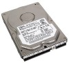
IBM IC35L040AVVN07-0 Hard Drive Specifications - Page 5

Table of contents - jumper

Page 5 highlights

Table of contents List of figures iii 1.0 General 1 1.1 Glossary 1 1.2 General caution 1 1.3 References 1 2.0 General features 3 Part 1. Functional specification 5 3.0 Fixed disk subsystem description 7 3.1 Control Electronics 7 3.2 Head disk assembly 7 3.3 Actuator 7 4.0 Drive characteristics 9 4.1 Default logical drive parameters 9 4.2 Data sheet 10 4.3 Drive organization 11 4.3.1 Drive format 11 4.3.2 Cylinder allocation 11 4.4 Performance characteristics 13 4.4.1 Command overhead 13 4.4.2 Mechanical positioning 13 4.4.3 Drive ready time 15 4.4.4 Data transfer speed 16 4.4.5 Throughput 17 4.4.6 Operating modes 18 5.0 Defect flagging strategy 19 6.0 Specification 21 6.1 Electrical interface 21 6.1.1 Connector location 21 6.1.2 Signal definition 22 6.1.3 Interface logic signal levels 25 6.2 Signal timings 26 6.2.1 Reset timings 26 6.2.2 PIO timings 27 6.2.3 Multiword DMA timings 29 6.2.4 Ultra DMA timings 30 6.2.5 Addressing of registers 38 6.2.6 Cabling 38 6.3 Jumper settings 39 6.3.1 Jumper pin location 39 6.3.2 Jumper pin identification 39 6.3.3 Jumper pin assignment 40 6.3.4 Jumper positions 41 6.4 Environment 45 6.4.1 Temperature and humidity 45 6.4.2 Corrosion test 46 Deskstar 120GXP hard disk drive specifications iii

  • 1
  • 2
  • 3
  • 4
  • 5
  • 6
  • 7
  • 8
  • 9
  • 10
  • 11
  • 12
  • 13
  • 14
  • 15
  • 16
  • 17
  • 18
  • 19
  • 20
  • 21
  • 22
  • 23
  • 24
  • 25
  • 26
  • 27
  • 28
  • 29
  • 30
  • 31
  • 32
  • 33
  • 34
  • 35
  • 36
  • 37
  • 38
  • 39
  • 40
  • 41
  • 42
  • 43
  • 44
  • 45
  • 46
  • 47
  • 48
  • 49
  • 50
  • 51
  • 52
  • 53
  • 54
  • 55
  • 56
  • 57
  • 58
  • 59
  • 60
  • 61
  • 62
  • 63
  • 64
  • 65
  • 66
  • 67
  • 68
  • 69
  • 70
  • 71
  • 72
  • 73
  • 74
  • 75
  • 76
  • 77
  • 78
  • 79
  • 80
  • 81
  • 82
  • 83
  • 84
  • 85
  • 86
  • 87
  • 88
  • 89
  • 90
  • 91
  • 92
  • 93
  • 94
  • 95
  • 96
  • 97
  • 98
  • 99
  • 100
  • 101
  • 102
  • 103
  • 104
  • 105
  • 106
  • 107
  • 108
  • 109
  • 110
  • 111
  • 112
  • 113
  • 114
  • 115
  • 116
  • 117
  • 118
  • 119
  • 120
  • 121
  • 122
  • 123
  • 124
  • 125
  • 126
  • 127
  • 128
  • 129
  • 130
  • 131
  • 132
  • 133
  • 134
  • 135
  • 136
  • 137
  • 138
  • 139
  • 140
  • 141
  • 142
  • 143
  • 144
  • 145
  • 146
  • 147
  • 148
  • 149
  • 150
  • 151
  • 152
  • 153
  • 154
  • 155
  • 156
  • 157
  • 158
  • 159
  • 160
  • 161
  • 162
  • 163
  • 164
  • 165
  • 166
  • 167
  • 168
  • 169
  • 170
  • 171
  • 172
  • 173
  • 174
  • 175
  • 176
  • 177
  • 178
  • 179
  • 180
  • 181
  • 182
  • 183
  • 184
  • 185
  • 186
  • 187
  • 188
  • 189
  • 190
  • 191
  • 192
  • 193
  • 194
  • 195
  • 196
  • 197
  • 198
  • 199
  • 200
  • 201
  • 202
  • 203
  • 204
  • 205
  • 206
  • 207
  • 208
  • 209
  • 210
  • 211

Table of contents
46
6.4.2
Corrosion test
............................................................
45
6.4.1
Temperature and humidity
.................................................
45
6.4
Environment
..................................................................
41
6.3.4
Jumper positions
.........................................................
40
6.3.3
Jumper pin assignment
...................................................
39
6.3.2
Jumper pin identification
..................................................
39
6.3.1
Jumper pin location
.......................................................
39
6.3
Jumper settings
...............................................................
38
6.2.6
Cabling
.................................................................
38
6.2.5
Addressing of registers
....................................................
30
6.2.4
Ultra DMA timings
........................................................
29
6.2.3
Multiword DMA timings
....................................................
27
6.2.2
PIO timings
..............................................................
26
6.2.1
Reset timings
............................................................
26
6.2
Signal timings
.................................................................
25
6.1.3
Interface logic signal levels
................................................
22
6.1.2
Signal definition
..........................................................
21
6.1.1
Connector location
.......................................................
21
6.1
Electrical interface
............................................................
21
6.0
Specification
................................................................
19
5.0
Defect flagging strategy
......................................................
18
4.4.6
Operating modes
.........................................................
17
4.4.5
Throughput
..............................................................
16
4.4.4
Data transfer speed
......................................................
15
4.4.3
Drive ready time
.........................................................
13
4.4.2
Mechanical positioning
....................................................
13
4.4.1
Command overhead
......................................................
13
4.4
Performance characteristics
....................................................
11
4.3.2
Cylinder allocation
........................................................
11
4.3.1
Drive format
.............................................................
11
4.3
Drive organization
.............................................................
10
4.2
Data sheet
....................................................................
9
4.1
Default logical drive parameters
...................................................
9
4.0
Drive characteristics
...........................................................
7
3.3
Actuator
........................................................................
7
3.2
Head disk assembly
.............................................................
7
3.1
Control Electronics
...............................................................
7
3.0
Fixed disk subsystem description
..............................................
5
Part 1. Functional specification
...............................................
3
2.0
General features
...............................................................
1
1.3
References
.....................................................................
1
1.2
General caution
.................................................................
1
1.1
Glossary
........................................................................
1
1.0
General
.......................................................................
iii
List of figures
.....................................................................
Deskstar 120GXP hard disk drive specifications
iii