IBM IC35L040AVVN07-0 Hard Drive Specifications - Page 83
Data Register, Device Control Register, Drive Address Register
 |
UPC - 683728124212
View all IBM IC35L040AVVN07-0 manuals
Add to My Manuals
Save this manual to your list of manuals |
Page 83 highlights
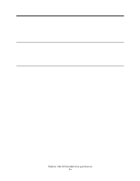
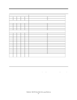
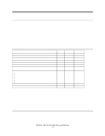
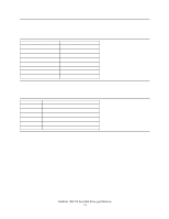
8.5 Data Register This register is used to transfer data blocks between the device data buffer and the host. It is also the register through which sector information is transferred on a Format Track command and configuration information is transferred on an Identify Device command. All data transfers are 16 bits wide, except for ECC byte transfers which are 8 bits wide. Data transfers are PIO only. The register contains valid data only when DRQ=1 in the Status Register. 8.6 Device Control Register Device Control Register 7 6 5 4 3 2 1 0 - - - - 1 SRST -IEN 0 Figure 70. Device Control Register Bit Definitions SRST (RST) Software Reset. The device is held reset when RST=1. Setting RST=0 re-enables the device. The host must set RST=1 and wait for at least 5 µs before setting RST=0 to ensure that the device recognizes the reset. -IEN Interrupt Enable. When -IEN=0 and the device is selected, device interrupts to the host will be enabled. When -IEN=1 or the device is not selected, device interrupts to the host will be disabled. 8.7 Drive Address Register Drive Address Register 7 6 5 4 3 2 1 0 HIZ -WTG -H3 -H2 -H1 -H0 -DS1 -DS0 Figure 71. Drive Address Register This register contains the inverted drive select and head select addresses of the currently selected drive. Bit Definitions HIZ High Impedance. This bit is not driven and will always be in a high impedance state. -WTG -Write Gate. This bit is 0 when writing to the disk device is in progress. -H3,-H2,-H1,-H0 -Head Select. These four bits are the 1's complement of the binary coded address of the currently selected head. -H0 is the least significant. Deskstar 120GXP hard disk drive specifications 69
-
 1
1 -
2
-
3
-
4
-
5
-
6
-
7
-
8
-
9
-
10
-
11
-
12
-
13
-
14
-
15
-
16
-
17
-
18
-
19
-
20
-
21
-
22
-
23
-
24
-
25
-
26
-
27
-
28
-
29
-
30
-
31
-
32
-
33
-
34
-
35
-
36
-
37
-
38
-
39
-
40
-
41
-
42
-
43
-
44
-
45
-
46
-
47
-
48
-
49
-
50
-
51
-
52
-
53
-
54
-
55
-
56
-
57
-
58
-
59
-
60
-
61
-
62
-
63
-
64
-
65
-
66
-
67
-
68
-
69
-
70
-
71
-
72
-
73
-
74
-
75
-
76
-
77
-
 78
78 -
 79
79 -
 80
80 -
 81
81 -
 82
82 -
 83
83 -
 84
84 -
 85
85 -
 86
86 -
 87
87 -
 88
88 -
89
-
90
-
91
-
92
-
93
-
94
-
95
-
96
-
97
-
98
-
99
-
100
-
101
-
102
-
103
-
104
-
105
-
106
-
107
-
108
-
109
-
110
-
111
-
112
-
113
-
114
-
115
-
116
-
117
-
118
-
119
-
120
-
121
-
122
-
123
-
124
-
125
-
126
-
127
-
128
-
129
-
130
-
131
-
132
-
133
-
134
-
135
-
136
-
137
-
138
-
139
-
140
-
141
-
142
-
143
-
144
-
145
-
146
-
147
-
148
-
149
-
150
-
151
-
152
-
153
-
154
-
155
-
156
-
157
-
158
-
159
-
160
-
161
-
162
-
163
-
164
-
165
-
166
-
167
-
168
-
169
-
170
-
171
-
172
-
173
-
174
-
175
-
176
-
177
-
178
-
179
-
180
-
181
-
182
-
183
-
184
-
185
-
186
-
187
-
188
-
189
-
190
-
191
-
192
-
193
-
194
-
195
-
196
-
197
-
198
-
199
-
200
-
201
-
202
-
203
-
204
-
205
-
206
-
207
-
208
-
209
-
210
-
211
 |
 |