IBM IC35L040AVVN07-0 Hard Drive Specifications - Page 87
General operation
 |
UPC - 683728124212
View all IBM IC35L040AVVN07-0 manuals
Add to My Manuals
Save this manual to your list of manuals |
Page 87 highlights
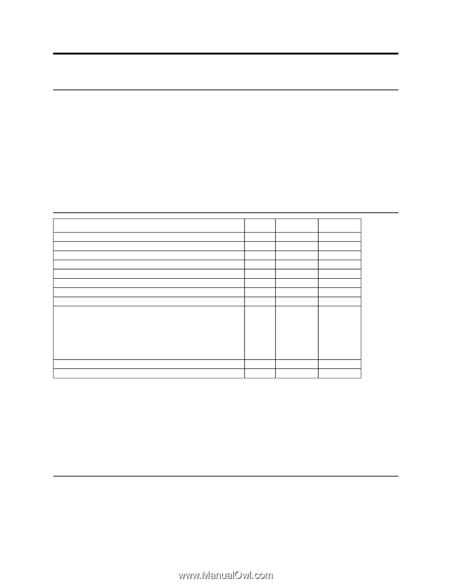
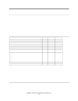
9.0 General operation 9.1 Reset response There are three types of resets in ATA: Power On Reset (POR). The device executes a series of electrical circuitry diagnostics, spins up the HDA, tests speed and other mechanical parameters, and sets default values. Hard Reset (Hardware Reset). RESET- signal is negated in ATA Bus. The device resets the interface circuitry as well as Soft Reset. Soft Reset (Software Reset). SRST bit in the Device Control Register is set and then is reset. The device resets the interface circuitry according to the Set Features requirement. The actions of each reset is shown in the following figure. Aborting Host interface Aborting Device interface Initialization of hardware Internal diagnostic Spinning spindle Initialization of registers (2) DASP handshake PDIAG handshake Reverting programmed parameters to default ! Number of CHS (set by Initialize Device Parameter) ! Multiple mode ! Write Cache ! Read look-ahead ! ECC bytes Disable Standby timer Power mode POR - - O O O O O O Hard Reset Soft Reset O O (1) (1) X X X X X X O O O X O O O (3) (3) O X X (5) (4) (4) O - execute X - not execute Notes: (1) Execute after the data in write cache has been written. (2) Default value on POR is shown in Figure 76 on page 74. (3) The Set Features command with Feature register = CCh enables the device to revert these para- meters to the power on defaults. (4) In the case of Sleep mode the device goes to Standby mode. In other cases the device does not change current mode. (5) Idle when Power-Up in Standby feature set is disabled. Standby when Power-Up in Standby feature set is enabled. Figure 75. Reset Response Table Deskstar 120GXP hard disk drive specifications 73
-
 1
1 -
2
-
3
-
4
-
5
-
6
-
7
-
8
-
9
-
10
-
11
-
12
-
13
-
14
-
15
-
16
-
17
-
18
-
19
-
20
-
21
-
22
-
23
-
24
-
25
-
26
-
27
-
28
-
29
-
30
-
31
-
32
-
33
-
34
-
35
-
36
-
37
-
38
-
39
-
40
-
41
-
42
-
43
-
44
-
45
-
46
-
47
-
48
-
49
-
50
-
51
-
52
-
53
-
54
-
55
-
56
-
57
-
58
-
59
-
60
-
61
-
62
-
63
-
64
-
65
-
66
-
67
-
68
-
69
-
70
-
71
-
72
-
73
-
74
-
75
-
76
-
77
-
78
-
79
-
80
-
81
-
 82
82 -
 83
83 -
 84
84 -
 85
85 -
 86
86 -
 87
87 -
 88
88 -
 89
89 -
 90
90 -
 91
91 -
 92
92 -
93
-
94
-
95
-
96
-
97
-
98
-
99
-
100
-
101
-
102
-
103
-
104
-
105
-
106
-
107
-
108
-
109
-
110
-
111
-
112
-
113
-
114
-
115
-
116
-
117
-
118
-
119
-
120
-
121
-
122
-
123
-
124
-
125
-
126
-
127
-
128
-
129
-
130
-
131
-
132
-
133
-
134
-
135
-
136
-
137
-
138
-
139
-
140
-
141
-
142
-
143
-
144
-
145
-
146
-
147
-
148
-
149
-
150
-
151
-
152
-
153
-
154
-
155
-
156
-
157
-
158
-
159
-
160
-
161
-
162
-
163
-
164
-
165
-
166
-
167
-
168
-
169
-
170
-
171
-
172
-
173
-
174
-
175
-
176
-
177
-
178
-
179
-
180
-
181
-
182
-
183
-
184
-
185
-
186
-
187
-
188
-
189
-
190
-
191
-
192
-
193
-
194
-
195
-
196
-
197
-
198
-
199
-
200
-
201
-
202
-
203
-
204
-
205
-
206
-
207
-
208
-
209
-
210
-
211
 |
 |