Icom ID-52A Ci-v Reference Guide english - Page 4
DTIP: CI-V connection example, REMOTE CONTROL, Connecting to a PC
 |
View all Icom ID-52A manuals
Add to My Manuals
Save this manual to your list of manuals |
Page 4 highlights
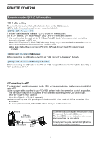
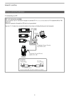
REMOTE CONTROL Remote control (CI-V) information DDConnecting to a PC TIP: CI-V connection example The transceiver can be connected through an optional CT-17 ci-v level converter to a PC equipped with an RS232C port. LLRemote operation through the [SP] jack is not guaranteed. See the CT-17 instruction manual for details of remotely controlling transceivers and receivers. Power supply 9 V~15 V DC PC RS-232C cable ct-17 2-conductor 3�5 mm (1/8 inch) plug must be used� ID-52A/E Connections ID-52A/E side 3�5 mm (1/8 inch) SP* GND* 3-conductor 3�5 mm (1/8 inch) plug must be used� CT-17 side 3�5 mm (1/8 inch) GND I/O I/O Less than 4�5 (d) mm To hear the receive audio, connect SP* and GND* to the speaker� 3
-
 1
1 -
 2
2 -
 3
3 -
 4
4 -
 5
5 -
 6
6 -
 7
7 -
 8
8 -
 9
9 -
 10
10 -
11
-
12
-
13
-
14
 |
 |

3
REMOTE CONTROL
Remote control (CI-V) information
D
Connecting to a PC
TIP: CI-V connection example
The transceiver can be connected through an optional CT-17
±I-v LEvEL ±²NvER³ER
to a PC equipped with an RS-
232C port�
L
Remote operation through the [SP] jack is not guaranteed�
See the CT-17 instruction manual for details of remotely controlling transceivers and receivers�
ID-52A/E
ct-17
Power supply
9 V
~
15 V DC
RS-232C
cable
PC
2-conductor 3�5 mm (1/8 inch)
plug must be used�
Connections
GND
*
I/O
SP
*
I/O
GND
Less than 4�5 (d) mm
ID-52A/E side
3�5 mm (1/8 inch)
CT-17 side
3�5 mm (1/8 inch)
To hear the receive audio, connect SP
*
and GND
*
to the speaker�
3-conductor 3�5 mm (1/8 inch)
plug must be used�