Image Fitness 17.0 R Treadmill English Manual - Page 7
Upright to the Upright Base 48 with two Upright Bolts
 |
View all Image Fitness 17.0 R Treadmill manuals
Add to My Manuals
Save this manual to your list of manuals |
Page 7 highlights
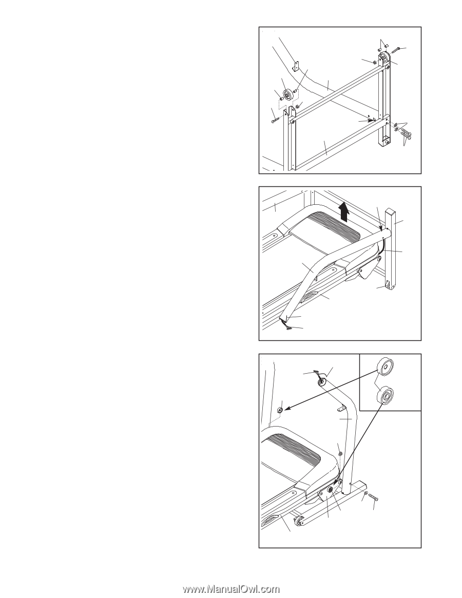
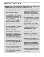
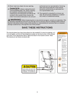
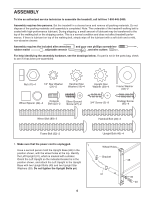
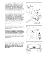
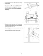
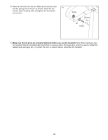
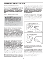
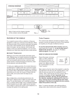
2. Orient the Right Upright (36) so the square hole near the lower end is in the position shown. Attach the Right Upright to the Upright Base (48) with two Upright Bolts (40) and two Upright Star Washers (39). Do not tighten the Upright Bolts yet. Attach each Wheel (45) to the Upright Base (48) with a Wheel Bolt (89), two Wheel Spacers (44), and a Nut (47) as shown. Do not overtighten the Wheel Bolts; the Wheels should turn freely. 2 45 44 89 44 36 47 44 89 47 45 Square Hole 48 39 40 3. Cut the tie securing the Wire Harness (28) in a bundle. Do not remove the large colored tie on the end of the Wire Harness. Orient the Upright Base (48) so the Wheels (45) are at the bottom. Next, position the Upright Base and the Uprights (31, 36) around the frame assembly as shown. Have another person lift the front of the frame assembly and hold it. Insert the Wire Harness (28) into the square hole near the lower end of the Right Upright (36) and out of the top. Next, raise the Uprights (31, 36) so the Upright Base (48) is flat on the floor. Make sure that the end of the Wire Harness does not fall into the Right Upright; it may be helpful to hold the colored tie on the end of the Wire Harness. 3 31 Hole 48 28 36 45 Frame Assembly Colored Tie 28 4. Open the included grease packet, and apply equal amounts of grease to both sides of each Frame Spacer (34). Hold one of the Frame Spacers (34) between the frame assembly and the Right Upright (36); make sure that the Frame Spacer is oriented as shown in the inset drawing. Insert a Frame Bolt (32) through a Frame Washer (33), the Right Upright, the Frame Spacer, and the bracket on the frame assembly. Be careful not to pinch the Wire Harness (28) in the Right Upright. Tighten a Nut (47) several turns onto the Frame Bolt, but do not fully tighten the Nut yet. Repeat this step on the left side. Note: There is not a wire harness on the left side. Remove the colored tie from the Wire Harness (28). 4 Colored Tie 28 34 34 36 47 33 34 32 59 Frame Assembly Left Side Right Side 7
-
 1
1 -
 2
2 -
 3
3 -
 4
4 -
 5
5 -
 6
6 -
 7
7 -
 8
8 -
 9
9 -
 10
10 -
 11
11 -
 12
12 -
13
-
14
-
15
-
16
-
17
-
18
-
19
-
20
-
21
-
22
-
23
-
24
-
25
-
26
 |
 |