Image Fitness 17.0 R Treadmill English Manual - Page 8
Console May Be Damaged When The Power
 |
View all Image Fitness 17.0 R Treadmill manuals
Add to My Manuals
Save this manual to your list of manuals |
Page 8 highlights
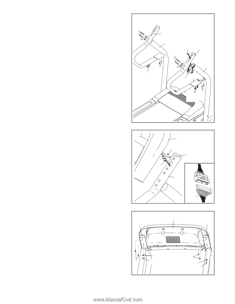
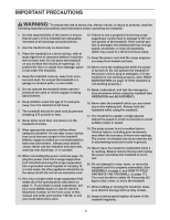
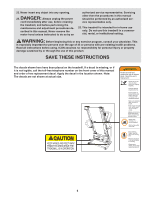
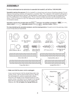
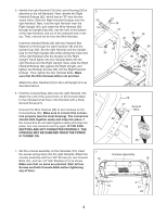
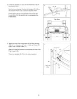
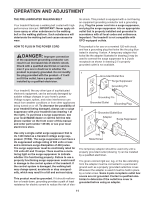
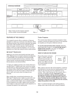
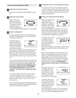
5. Identify the right Handrail (18) (the Latch Housing [30] is attached to the left Handrail). Next, identify the Right Handrail Endcap (92), which has an "R" near the two screw holes. Slide the Right Handrail Endcap onto the right Handrail. Next, hold the right Handrail near the Right Upright (36), and insert the Wire Harness (28) through an Upright Cap (90), into the hole in the bottom of the right Handrail, and out of the indicated hole in the top. Then, remove the tie from the Wire Harness. Insert two Handrail Bolts (20) with two Handrail Star Washers (19) through the right Handrail (18) and the Upright Cap (90). Set the right Handrail and the Upright Cap on the Right Upright (36) while sliding the lower end of the right Handrail onto the bracket on the Right Upright. Hand tighten the two Handrail Bolts into the right Handrail and the Right Upright. Next, slide the Right Handrail Endcap (92) against the Right Upright, and tighten two Endcap Screws (95) into the Right Handrail Endcap. Then, tighten the two Handrail Bolts. Make sure that the Wire Harness (28) is not pinched. Attach the other Handrail (18) to the Left Upright (31) as described above. 6. Hold the Console Base (26) near the right Handrail (18). Attach the end of the ground wire on the Console Base to the indicated small hole in the Handrail with a Silver Ground Screw (27). Connect the Wire Harness (28) to wire harness on the Console Base (26). Make sure to connect the connectors properly (see the inset drawing). The connectors should slide together easily and snap into place. If the connectors do not slide together easily and snap into place, turn one connector and try again. IF THE CONNECTORS ARE NOT CONNECTED PROPERLY, THE CONSOLE MAY BE DAMAGED WHEN THE POWER IS TURNED ON. 5 20 18 19 31 28 18 20 95 19 36 30 92 90 Screw 95 Holes 6 26 27 Ground Wire 28 18 28 7. Set the console assembly on the Handrails (18); insert 7 the excess wiring down into the right Handrail. Attach the Console Assembly console assembly with four 3/4" Screws (2), two Console 18 18 Bolts (22), and two 1/4" Star Washers (21) as shown. Make sure that no wires are pinched. Start all four Screws and both Console Bolts before tightening any of them. 21 2 22 2 21 22 8
-
 1
1 -
2
-
 3
3 -
 4
4 -
 5
5 -
 6
6 -
 7
7 -
 8
8 -
 9
9 -
 10
10 -
 11
11 -
 12
12 -
 13
13 -
14
-
15
-
16
-
17
-
18
-
19
-
20
-
21
-
22
-
23
-
24
-
25
-
26
 |
 |