Image Fitness 5.0 Bench User Manual - Page 7
Attach the Center Upright 3 to the Center Base
 |
View all Image Fitness 5.0 Bench manuals
Add to My Manuals
Save this manual to your list of manuals |
Page 7 highlights
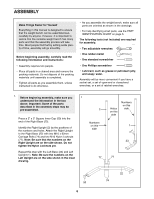
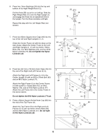
2. Press two 50mm Thick Square Inner Caps (53) and a 2" x 3" Inner Cap (50) into the ends of the Center Base (24). Have a second person hold the Right and Left Uprights (1, 2 [not shown]). Attach the Right and Left Bases (22, 23) to the Center Base (24) with two M10 x 97mm Bolts (90) and two M10 Nylon Locknuts (77). Do not tighten the Nylon Locknuts yet. 3. Press two 2" Round Inner Caps (47) into the ends of the weight tube on the Weight Carriage (25). Press two 75mm Bushings (26) into the top and bottom of the Weight Carriage. Orient the Weight Carriage (25) and Center Upright (3) so that the welded bolt and letters are on the indicated sides. Slide the Weight Carriage onto the bottom of the Center Upright. Attach the Carriage Stop (27) to the indicated hole in the Center Upright (3) with an M10 x 86mm Bolt (63) and an M10 Nylon Locknut (77). 4. Attach the Center Upright (3) to the Center Base (24) with two M10 x 75mm Bolts (73), four M10 Washers (79), and two M10 Nylon Locknuts (77). Do not tighten the Nylon Locknuts yet. 2 22 77 77 53 24 53 3 Letters near the top of this side 77 3 26 47 Weight 25 Tube 26 27 4 77 79 3 1 50 90 23 90 63 Welded Bolt 47 79 73 24 5. Press two 75mm Bushings (26) into the top and 5 bottom of the Safety Spotter (10). Attach the two Safety Spotter Bumpers (34) to the Safety Spotter (10) with two M10 x 25mm Button Bolts (81), two M10 Washers (79), and two M10 Nylon Locknuts (77). Pull the Knob (30) out as far as it will go. Slide the Safety Spotter (10) onto the top of the Center Upright (3) and engage the Knob into an adjustment hole. Turn the Knob clockwise until tight. Press a 60mm Square Inner Cap (46) into the top of the Center Upright (3). 7 26 77 34 79 81 26 3 46 10 30 77 34 79 81 Adjustment Hole
-
 1
1 -
 2
2 -
 3
3 -
 4
4 -
 5
5 -
 6
6 -
 7
7 -
 8
8 -
 9
9 -
 10
10 -
 11
11 -
 12
12 -
13
-
14
-
15
-
16
-
17
-
18
-
19
-
20
-
21
-
22
-
23
-
24
-
25
-
26
 |
 |
