Image Fitness 5.0 Bench User Manual - Page 9
Attach the Pull-up Bar to the Right Frame 5
 |
View all Image Fitness 5.0 Bench manuals
Add to My Manuals
Save this manual to your list of manuals |
Page 9 highlights
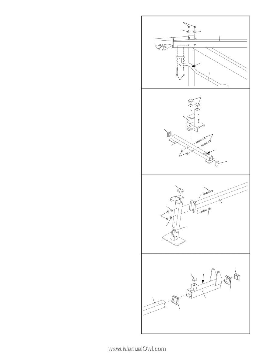
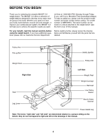
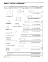
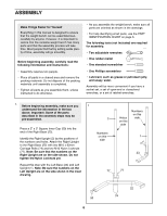
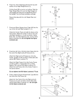
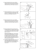
10. Orient the Pull-up Bar (8) with the bend on top. Attach the Pull-up Bar to the Right Frame (5) with two M10 x 57mm Bolts (78), two M10 Washers (79), and two M10 Nylon Locknuts (77). Do not tighten the Nylon Locknuts yet. Attach the Pull-up Bar (8) to the Left Frame (not shown) in the same manner. Tighten the M10 Nylon Locknuts (77) used in steps 1-10. 11. Press two 38mm x 50mm Inner Caps (52) into the top of the Back Leg (39). Press two 50mm Square Inner Caps (51) into the ends of the Stabilizer (40). Orient the Stabilizer (40) so the decal is in the position shown. Attach the Back Leg (39) to the Stabilizer with two M10 x 62mm Carriage Bolts (74) and two M10 Nylon Locknuts (77). Do not tighten the Nylon Locknuts yet. 10 77 79 78 11 39 51 40 77 79 5 Top 8 52 74 Decal 51 12. Press a 60mm Square Inner Cap (46) into the top of the Front Leg (18). Orient the Bench Frame (14) as shown. Attach the Bench Frame to the Front Leg (18) with two M10 x 78mm Bolts (70), two M10 Washers (79), and two M10 Nylon Locknuts (77). Do not tighten the Nylon Locknuts yet. 12 46 79 77 79 70 14 70 18 13. Press a 38mm x 50mm Inner Cap (64) into the indicated part of the Sliding Seat Frame (15). Press two 75mm Bushings (26) into the ends of the Sliding Seat Frame. Orient the Sliding Seat Frame (15) as shown. Pull the Knob (not shown) out as far as it will go. Slide the Sliding Seat Frame onto the Bench Frame (14) and engage the Knob into an adjustment hole in the Bench Frame. Press a 60mm Square Angled Inner Cap (95) into the end of the Bench Frame (14). 13 14 9 95 64 Knob 26 15 26
-
 1
1 -
2
-
3
-
 4
4 -
 5
5 -
 6
6 -
 7
7 -
 8
8 -
 9
9 -
 10
10 -
 11
11 -
 12
12 -
 13
13 -
 14
14 -
15
-
16
-
17
-
18
-
19
-
20
-
21
-
22
-
23
-
24
-
25
-
26
 |
 |