Intel BOXD510MO Product Guide - Page 36
Connecting to the S/PDIF Header, Connecting to the Parallel Port Header, Table 8. S/PDIF Header
 |
View all Intel BOXD510MO manuals
Add to My Manuals
Save this manual to your list of manuals |
Page 36 highlights
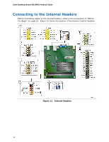
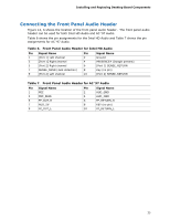
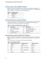
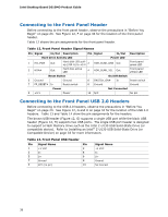
Intel Desktop Board D510MO Product Guide Connecting to the S/PDIF Header Before connecting to the S/PDIF connector, observe the precautions in "Before You Begin" on page 23. See Figure 12, B on page 34 for the location of the S/PDIF header. Table 8 shows the pin assignments for the S/PDIF header. Table 8. S/PDIF Header Pin Signal Name 1 Ground 2 S/PDIF out 3 VCC (5V) Connecting to the Serial Headers Before connecting to the serial headers, observe the precautions in "Before You Begin" on page 23. See Figure 12, C on page 34 for the location of the serial headers. Table 9 shows the pin assignments for the serial headers. Table 9. Serial Port Headers (COM 1 and COM 2) Pin Signal Name Pin Signal Name 1 DCD (Data Carrier Detect) 2 RXD# (Receive Data) 3 TXD# (Transmit Data) 4 DTR (Data Terminal Ready) 5 Ground 7 RTS (Request To Send) 9 RI (Ring Indicator) 6 DSR (Data Set Ready) 8 CTS (Clear To Send) 10 Key (no pin) Connecting to the Parallel Port Header Before connecting to the parallel port header, observe the precautions in "Before You Begin" on page 23. See Figure 12, D on page 34 for the location of the parallel port header. Table 10 shows the pin assignments for the parallel port header. Table 10. Parallel Port Header Pin Standard Signal Name 1 STROBE# 2 AUTOFD# 3 PD0 4 FAULT# 5 PD1 6 INT# 7 PD2 8 SLCTIN# ECP Signal Name STROBE# AUTOFD#, HOSACK PD0 FAULT#, PERIPHREQST# PD1 INT#, REVERSERQST# PD2 SLCTIN# EPP Signal Name WRITE# DATASTB# PD0 FAULT# PD1 RESET# PD2 ADDRSTB# 36
-
 1
1 -
2
-
3
-
4
-
5
-
6
-
7
-
8
-
9
-
10
-
11
-
12
-
13
-
14
-
15
-
16
-
17
-
18
-
19
-
20
-
21
-
22
-
23
-
24
-
25
-
26
-
27
-
28
-
29
-
30
-
 31
31 -
 32
32 -
 33
33 -
 34
34 -
 35
35 -
 36
36 -
 37
37 -
 38
38 -
 39
39 -
 40
40 -
 41
41 -
42
-
43
-
44
-
45
-
46
-
47
-
48
-
49
-
50
-
51
-
52
-
53
-
54
-
55
-
56
-
57
-
58
-
59
-
60
-
61
-
62
-
63
-
64
-
65
-
66
 |
 |
