Intel BOXD510MO Product Guide - Page 37
Connecting to the Front Panel Wireless Activity LED Header
 |
View all Intel BOXD510MO manuals
Add to My Manuals
Save this manual to your list of manuals |
Page 37 highlights
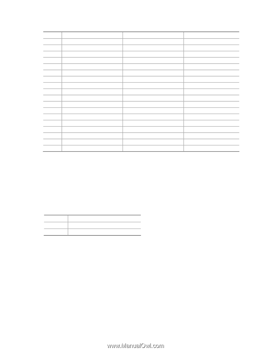
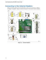
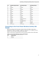
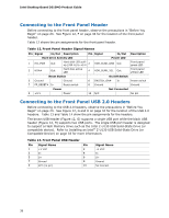
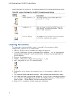
Installing and Replacing Desktop Board Components Pin 9 10 11 12 13 14 15 16 17 18 19 20 21 22 23 24 25 26 Standard Signal Name PD3 GROUND PD4 GROUND PD5 GROUND PD6 GROUND PD7 GROUND ACK# GROUND BUSY GROUND PERROR GROUND SELECT KEY (no pin) ECP Signal Name PD3 GROUND PD4 GROUND PD5 GROUND PD6 GROUND PD7 GROUND ACK# GROUND BUSY#, PERIPHACK GROUND PE, ACKREVERSE# GROUND SELECT KEY (no pin) EPP Signal Name PD3 GROUND PD4 GROUND PD5 GROUND PD6 GROUND PD7 GROUND INTR GROUND WAIT# GROUND PE GROUND SELECT KEY (no pin) Connecting to the Front Panel Wireless Activity LED Header Before connecting to the front panel wireless activity LED header, observe the precautions in "Before You Begin" on page 23. See Figure 12, E on page 34 for the location of the front panel wireless activity LED header. Table 11 shows the pin assignments for the front panel wireless activity LED header. Table 11. Front Panel Wireless Activity LED Header Pin Signal Name 1 LED (+) 2 Ground 37
-
 1
1 -
2
-
3
-
4
-
5
-
6
-
7
-
8
-
9
-
10
-
11
-
12
-
13
-
14
-
15
-
16
-
17
-
18
-
19
-
20
-
21
-
22
-
23
-
24
-
25
-
26
-
27
-
28
-
29
-
30
-
31
-
 32
32 -
 33
33 -
 34
34 -
 35
35 -
 36
36 -
 37
37 -
 38
38 -
 39
39 -
 40
40 -
 41
41 -
 42
42 -
43
-
44
-
45
-
46
-
47
-
48
-
49
-
50
-
51
-
52
-
53
-
54
-
55
-
56
-
57
-
58
-
59
-
60
-
61
-
62
-
63
-
64
-
65
-
66
 |
 |