Intel DH55TC DH55TC Technical Product Specification
Intel DH55TC Manual
 |
View all Intel DH55TC manuals
Add to My Manuals
Save this manual to your list of manuals |
Intel DH55TC manual content summary:
- Intel DH55TC | DH55TC Technical Product Specification - Page 1
January 2010 Order Number: E81940-001US The Intel® Desktop Board DH55TC may contain design defects or errors known as errata that may cause the product to deviate from published specifications. Current characterized errata are documented in the Intel Desktop Board DH55TC Specification Update. - Intel DH55TC | DH55TC Technical Product Specification - Page 2
Intel® Desktop Board DH55TC with BIOS identifier TCIBX10H.86A. Changes to this specification will be published in the Intel Desktop Board DH55TC Specification Update before being incorporated into a revision of this document. INFORMATION IN THIS DOCUMENT IS PROVIDED IN CONNECTION WITH INTEL - Intel DH55TC | DH55TC Technical Product Specification - Page 3
Desktop Board The features supported by the BIOS Setup program A description of the BIOS error messages, beep codes, and POST codes Regulatory compliance and battery disposal information Typographical Conventions This section contains information about the conventions used in this specification - Intel DH55TC | DH55TC Technical Product Specification - Page 4
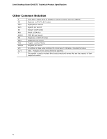
Intel Desktop Board DH55TC Technical Product Specification Other Common Notation # GB GB/s Gb/s KB Kbit kbits/s MB second Megabit (1,048,576 bits) Megabits per second An address or data value ending with a lowercase h indicates a hexadecimal value. Volts. Voltages are DC unless otherwise specified - Intel DH55TC | DH55TC Technical Product Specification - Page 5
Support 14 1.4 Processor 14 1.5 Intel® H55 Express Chipset 15 1.6 System Memory 15 1.6.1 Memory Configurations 16 1.7 Graphics Subsystem 18 1.7.1 Integrated Graphics 18 1.7.2 PCI Express x16 Graphics 19 1.8 USB 19 1.9 SATA Interfaces 20 1.10 Legacy I/O Controller 20 1.10.1 Serial Port - Intel DH55TC | DH55TC Technical Product Specification - Page 6
Drive Boot 64 3.6.2 Network Boot 64 3.6.3 Booting Without Attached Devices 64 3.6.4 Changing the Default Boot Device During POST 64 3.7 BIOS Security Features 65 4 Error Messages and Beep Codes 4.1 Speaker 67 4.2 BIOS Beep Codes 67 4.3 Front-panel Power LED Blink Codes 68 4.4 BIOS Error - Intel DH55TC | DH55TC Technical Product Specification - Page 7
AC '97 Audio 42 16. Front Panel USB Header 42 17. Front Panel USB Header (with Intel Z-U130 USB Solid-State Drive, or Compatible Device, Support 43 18. SATA Connectors 43 19. Processor (4-Pin) Fan Header 43 20. Front and Rear Chassis Fan Headers 43 21. Processor Core Power Connector 44 22 - Intel DH55TC | DH55TC Technical Product Specification - Page 8
/Media Types for BIOS Recovery 63 35. Boot Device Menu Options 64 36. Supervisor and User Password Functions 65 37. BIOS Beep Codes 67 38. Front-panel Power LED Blink Codes 68 39. BIOS Error Messages 68 40. Port 80h POST Code Ranges 69 41. Port 80h POST Codes 70 42. Typical Port 80h POST - Intel DH55TC | DH55TC Technical Product Specification - Page 9
Solid-State Drive (or compatible device) • Six internal Serial ATA (SATA) 3.0 Gb/s ports: ― Two ports compatible with eSATA dongles • One serial port header • One parallel port header • One back panel PS/2 connector • Intel® BIOS resident in the SPI Flash device • Support for Advanced Configuration - Intel DH55TC | DH55TC Technical Product Specification - Page 10
Board DH55TC Technical Product Specification Table 1. Feature Summary (continued) Instantly Available PC Technology • Support for PCI* Local Bus Specification Revision 2.3 • Support for PCI Express* • Suspend to RAM support • Wake on PCI, PCI Express, LAN, front panel, PS/2, serial and USB ports - Intel DH55TC | DH55TC Technical Product Specification - Page 11
Product Description 1.1.2 Board Layout Figure 1 shows the location of the major components on Intel Desktop Board DH55TC. Figure 1. Major Board Components Table 2 lists the components identified in Figure 1. 11 - Intel DH55TC | DH55TC Technical Product Specification - Page 12
Standby power LED T Front panel USB header with support for an Intel Z-U130 USB Solid-State Drive (or compatible device) U Front panel USB headers (2) V Parallel port header W Intel H55 Express Chipset X Piezoelectric speaker Y Serial port header Z S/PDIF header AA Front panel audio - Intel DH55TC | DH55TC Technical Product Specification - Page 13
Product Description 1.1.3 Block Diagram Figure 2 is a block diagram of the major functional areas of the board. Figure 2. Block Diagram 13 - Intel DH55TC | DH55TC Technical Product Specification - Page 14
ATA (PATA) IDE drive connector 1.3 Online Support To find information about... Intel Desktop Board DH55TC Desktop Board Support Available configurations for the Intel Desktop Board DH55TC Supported processors Chipset information BIOS and driver updates Tested memory Integration information Visit - Intel DH55TC | DH55TC Technical Product Specification - Page 15
with all applicable DDR SDRAM memory specifications, the board should be populated with DIMMs that support the Serial Presence Detect (SPD) data structure. This allows the BIOS to read the SPD data and program the chipset to accurately configure memory settings for optimum performance. If non - Intel DH55TC | DH55TC Technical Product Specification - Page 16
Intel Desktop Board DH55TC Technical Product Specification For information about... Tested Memory Refer to: http://www.intel.com/support/motherboards/desktop/sb/CS025414.htm 1.6.1 Memory Configurations The Intel Core i7, Intel Core i5, Intel Core i3, and Intel Pentium processors support the - Intel DH55TC | DH55TC Technical Product Specification - Page 17
Description Figure 3 illustrates the memory channel and DIMM configuration. Figure 3. Memory Channel and DIMM Configuration NOTE When using a processor without Intel Graphics Technology: there must always be memory installed into any or both of the DIMM 0 (blue) memory slots for the system to - Intel DH55TC | DH55TC Technical Product Specification - Page 18
processors with Intel Graphics Technology. NOTE The Intel Desktop Board DH55TC supports connectivity of up to three monitors through its diverse integrated graphics ports, however only up to two monitors can be simultaneously enabled. Environments not supported by the graphics driver (i.e., POST - Intel DH55TC | DH55TC Technical Product Specification - Page 19
DVI 1.0 specification. The DVI-D port is only enabled for POST when there are no monitors attached to the VGA or HDMI connectors. 1.7.2 PCI Express x16 Graphics The Intel Core i7, Intel Core i5, Intel Core i3, and Intel Pentium processors in an LGA1156 socket support discrete add in graphics cards - Intel DH55TC | DH55TC Technical Product Specification - Page 20
wake-up event interface • PCI Conventional bus power management support The BIOS Setup program provides configuration options for the Legacy I/O controller. 1.10.1 Serial Port The serial port is implemented as a 10-pin header on the board. The serial port supports data transfers at speeds up - Intel DH55TC | DH55TC Technical Product Specification - Page 21
as a 26-pin header on the board. Use the BIOS Setup program to set the parallel port mode. For information about The location of the parallel port header Refer to Figure 10, page 39 1.11 Audio Subsystem The board supports Intel High Definition Audio via the HDMI interface as well as via the - Intel DH55TC | DH55TC Technical Product Specification - Page 22
Intel Desktop Board DH55TC Technical Product Specification 1.11.2.1 Analog Audio Connectivity The available configurable back panel audio connectors are shown in Figure 4. Item A B C Description Audio line in Audio line out Mic in Figure 4. Back Panel Audio Connector Options The back panel audio - Intel DH55TC | DH55TC Technical Product Specification - Page 23
) • Transmit TCP segmentation • Full device driver compatibility • PCI Express power management support 1.12.2 LAN Subsystem Software LAN software and drivers are available from Intel's World Wide Web site. For information about Obtaining LAN software and drivers Refer to http://downloadcenter - Intel DH55TC | DH55TC Technical Product Specification - Page 24
Intel Desktop Board DH55TC Technical Product Specification 1.12.3 RJ-45 LAN Connector with Integrated LEDs Two LEDs are built into the RJ-45 LAN connector (shown in Figure 5). Item A B Description Link/Activity LED (green) Link Speed LED (green/yellow) Figure 5. LAN Connector LED Locations Table - Intel DH55TC | DH55TC Technical Product Specification - Page 25
supply 5V STBY rail. NOTE If the battery and AC power fail date and time values will be reset and the user will be notified during POST. When the voltage drops below a certain level, the BIOS Setup program settings stored in CMOS RAM (for example, the date and time) might not be accurate. Replace - Intel DH55TC | DH55TC Technical Product Specification - Page 26
Intel Desktop Board DH55TC Technical Product Specification 1.14.3 Thermal Monitoring Figure 6 shows the locations of the thermal sensors and fan headers. Item A B C D Description Rear chassis fan header Thermal diode, located on processor die Processor fan header Front chassis fan header Figure - Intel DH55TC | DH55TC Technical Product Specification - Page 27
(some add-in boards may require an ACPI-aware driver), video displays, and hard disk drives • Methods for achieving less than 15-watt system operation in the power-on/standby sleeping state • A Soft-off feature that enables the operating system to power-off the computer • Support for multiple wake - Intel DH55TC | DH55TC Technical Product Specification - Page 28
-power state. Table 6 lists the power states supported by the board along with the associated system power targets. See the ACPI specification for a complete description of the various system and power states. Table 6. Power States and Targeted System Power Global States Sleeping States Processor - Intel DH55TC | DH55TC Technical Product Specification - Page 29
events that can wake the computer from specific states. Table 7. Wake-up Devices and Events These devices/events can wake up the computer... Power switch RTC alarm LAN USB PME# signal WAKE# signal PS/2 Serial Notes: • S4 implies operating system support only. • USB ports are turned off during S4/S5 - Intel DH55TC | DH55TC Technical Product Specification - Page 30
Intel Desktop Board DH55TC Technical Product Specification 1.15.2 Hardware Support CAUTION Ensure that the power supply provides adequate +5 V standby current if LAN wake capabilities and Instantly Available PC technology features are used. Failure to do so can damage the power supply. The total - Intel DH55TC | DH55TC Technical Product Specification - Page 31
have a +12 V DC connection • 4-pin fan headers are controlled by Pulse Width Modulation • The front fan and rear fan headers also support linear fan control on 3-wire page 26 1.15.2.3 LAN Wake Capabilities CAUTION For LAN wake capabilities, the +5 V standby line for the power supply must be capable - Intel DH55TC | DH55TC Technical Product Specification - Page 32
panel power LED will behave as configured by the BIOS "S3 State Indicator" option). When signaled by a wake-up device or event, the system quickly returns to its last known wake state. Table 7 on page 29 lists the devices and events that can wake the computer from the S3 state. The board supports - Intel DH55TC | DH55TC Technical Product Specification - Page 33
Serial port activity wakes the computer from an ACPI S1 or S3 state. 1.15.2.10 +5 V Standby Power Indicator LED The +5 V standby power indicator LED shows that power is still present even when the computer appears to be off. Figure 7 shows the location of the standby power indicator LED on the board - Intel DH55TC | DH55TC Technical Product Specification - Page 34
two governmental agencies in the definition of new requirements. Intel Desktop Board DH55TC meets the following program requirements in an adequate system configuration, including appropriate selection of an efficient power supply: • Energy Star v5.0, category A • EPEAT* • Korea e-Standby • European - Intel DH55TC | DH55TC Technical Product Specification - Page 35
(40 MB) • Front side bus interrupts (17 MB) • PCI Express configuration space (256 MB) • PCH base address registers PCI Express ports (up to 256 MB) • Memory-mapped I/O that is dynamically allocated for PCI Conventional and PCI Express add-in cards (256 MB) The board provides the capability to - Intel DH55TC | DH55TC Technical Product Specification - Page 36
Intel Desktop Board DH55TC Technical Product Specification Figure 8. Detailed System Memory Address Map 36 - Intel DH55TC | DH55TC Technical Product Specification - Page 37
on video adapter used. Video memory and BIOS Extended BIOS data (movable by memory manager software) Extended conventional memory Conventional memory 2.2 Connectors and Headers CAUTION Only the following connectors and headers have overcurrent protection: back panel and front panel USB and - Intel DH55TC | DH55TC Technical Product Specification - Page 38
Intel Desktop Board DH55TC Technical Product Specification 2.2.1 Back Panel Connectors Figure 9 shows the location of the back panel connectors for the board. Item A B C D E F G H I J K Description PS/2 keyboard/mouse port USB ports VGA port DVI-D connector HDMI connector USB ports LAN USB ports - Intel DH55TC | DH55TC Technical Product Specification - Page 39
Technical Reference 2.2.2 Component-side Connectors and Headers Figure 10 shows the locations of the component-side connectors and headers. Figure 10. Component-side Connectors and Headers Table 9 lists the component-side connectors and headers identified in Figure 10. 39 - Intel DH55TC | DH55TC Technical Product Specification - Page 40
SATA connectors Alternate front panel power LED header Front panel header M USB header with support for an Intel Z-U130 USB Solid-State Drive (or compatible device) N USB headers (2) O Parallel port header P Serial port header Q S/PDIF header R Front panel audio header S Internal mono - Intel DH55TC | DH55TC Technical Product Specification - Page 41
Serial Port Header Pin Signal Name 1 DCD (Data Carrier Detect) 3 TXD# (Transmit Data) 5 Ground 7 RTS (Request To Send) 9 RI (Ring Indicator) Pin 2 4 6 8 10 Signal Name RXD# (Receive Data) DTR (Data Terminal Ready) DSR (Data Set DATASTB# PD0 FAULT# PD1 RESET# PD2 ADDRSTB# PD3 GROUND PD4 - Intel DH55TC | DH55TC Technical Product Specification - Page 42
Intel Desktop Board DH55TC Technical Product Specification Table 12. S/PDIF Header Pin Signal Name 1 Ground 2 S/PDIF out 3 Key (no pin) 3 +5V_DC Table 13. Internal Mono Speaker Header Pin Signal Name 1 − 2 + Table 14. Front Panel Audio Header for Intel HD Audio Pin Signal Name - Intel DH55TC | DH55TC Technical Product Specification - Page 43
Table 17. Front Panel USB Header (with Intel Z-U130 USB Solid-State Drive, or Compatible Device, Support) Pin Processor (4-Pin) Fan Header Pin Signal Name 1 Ground 2 +12 V 3 FAN_TACH 4 FAN_CONTROL Table 20. Front and Rear Chassis Fan Headers Pin 4-Wire Support Pin 3-Wire Support - Intel DH55TC | DH55TC Technical Product Specification - Page 44
Intel Desktop Board DH55TC Technical Product Specification 2.2.2.2 Add-in Card Connectors The board has the following add-in card connectors: • One PCI Express 2.0 x16: this connector supports simultaneous transfer speeds of up to 8 GB/s of peak bandwidth per direction. • Two PCI Express 2.0 x1: - Intel DH55TC | DH55TC Technical Product Specification - Page 45
Connector Pin Signal Name Pin 1 +3.3 V 13 2 +3.3 V 14 3 Ground 15 4 +5 V 16 5 Ground 17 6 +5 V 18 7 Ground 19 8 PWRGD (Power Good) 20 9 +5 V (Standby) 21 10 +12 V 22 11 +12 V (Note) 23 12 +3.3 V 2 x 12 connector detect 24 (Note) Signal Name +3.3 V −12 V Ground - Intel DH55TC | DH55TC Technical Product Specification - Page 46
be connected to an LED to provide a visual indicator that data is being read from or written to an internal storage device. Proper LED function requires a SATA hard drive or optical drive connected to an onboard SATA connector, or the use of an Intel Z-U130 Solid-State Drive (or compatible device - Intel DH55TC | DH55TC Technical Product Specification - Page 47
options are available through BIOS setup. Table 24. States for a One-Color Power LED LED State Description Off Power off/sleeping Steady Lit Running Blink Standby 2.2.2.4.4 Power Switch Header Pins 6 and 8 can be connected to a front panel momentary-contact power switch. The switch must - Intel DH55TC | DH55TC Technical Product Specification - Page 48
• Use only a front panel USB connector that conforms to the USB 2.0 specification for high-speed USB devices. Figure 12. Connection Diagram for Front Panel USB Headers Figure 13. Connection Diagram for Front Panel USB Header (with Intel Z-U130 USB Solid-State Drive, or Compatible Device, Support) 48 - Intel DH55TC | DH55TC Technical Product Specification - Page 49
the power cord from the computer before changing a jumper setting. Otherwise, the board could be damaged. Figure 14 shows the location of the jumper block. The 3-pin jumper block determines the BIOS Setup program's mode. Table 26 describes the jumper settings for the three modes: normal, configure - Intel DH55TC | DH55TC Technical Product Specification - Page 50
Intel Desktop Board DH55TC Technical Product Specification Table 26. BIOS Setup Configuration Jumper Settings Function/Mode Normal Jumper Setting 1-2 Configuration The BIOS uses current configuration information and passwords for booting. Configure 2-3 Recovery None After the POST runs, - Intel DH55TC | DH55TC Technical Product Specification - Page 51
is designed to fit into a MicroATX form-factor chassis. Figure 15 illustrates the mechanical form factor for the board. Dimensions are given in inches [millimeters]. The outer dimensions are 9.60 inches by 9.60 inches [243.84 millimeters by 243.84 millimeters]. Location of the I/O - Intel DH55TC | DH55TC Technical Product Specification - Page 52
Section 1.4 on page 14 for information on supported processors), up to 16 GB DDR3 memory, integrated graphics, one hard disk drive, one optical drive, and all board peripherals enabled, the minimum recommended power supply is about 320 W with current ratings as listed in Table 27. Table 27. Minimum - Intel DH55TC | DH55TC Technical Product Specification - Page 53
fan header. Connecting the processor fan to a chassis fan header may result in onboard component damage that will halt fan operation. Table 28 lists the current capability of the fan headers. Table 28. Fan Header Current Capability Fan Header Maximum Available Current Processor fan Front chassis - Intel DH55TC | DH55TC Technical Product Specification - Page 54
Intel Desktop Board DH55TC Technical Product Specification 2.6 Thermal Considerations CAUTION Use of a processor heat sink that provides omni-directional airflow to maintain required airflow across the processor voltage regulator area is highly recommended. CAUTION Failure to ensure appropriate - Intel DH55TC | DH55TC Technical Product Specification - Page 55
C Description Processor voltage regulator area Processor Intel H55 Express Chipset Figure board. Table 29. Thermal Considerations for Components Component Maximum Case Temperature Processor For processor case temperature, see processor datasheets and processor specification updates Intel H55 - Intel DH55TC | DH55TC Technical Product Specification - Page 56
30. Tcontrol Values for Components Component Tcontrol Processor For processor case temperature, see processor datasheets and processor specification updates Intel H55 Express Chipset 107 oC For information about Processor datasheets and specification updates Refer to Section 1.3, page 14 56 - Intel DH55TC | DH55TC Technical Product Specification - Page 57
is calculated from predicted data at 50 ºC. The MTBF for the board is 146,986 hours. 2.8 Environmental Table 31 lists the environmental specifications for the board. Table 31. Environmental Specifications Parameter Temperature Non-Operating Operating Shock Unpackaged Packaged Vibration Unpackaged - Intel DH55TC | DH55TC Technical Product Specification - Page 58
Intel Desktop Board DH55TC Technical Product Specification 58 - Intel DH55TC | DH55TC Technical Product Specification - Page 59
board uses an Intel BIOS that is stored in a 64 Mbit (8,192 KB) Serial Peripheral Interface Flash Memory (SPI Flash) device which can be updated using a set of utilities. The SPI Flash contains the BIOS Setup program, POST, LAN EEPROM information, Plug and Play support, and other firmware. The BIOS - Intel DH55TC | DH55TC Technical Product Specification - Page 60
Intel Desktop Board DH55TC Technical Product Specification Table 32 lists the BIOS Setup program menu features. Table 32. BIOS Setup Program Menu Bar Maintenance Main Advanced Performance Security Clears passwords and displays processor information Displays processor and memory configuration - Intel DH55TC | DH55TC Technical Product Specification - Page 61
peripherals, serial numbers, and asset tags • Resource data, such as memory size, cache size, and processor speed • Dynamic data, such as event detection and error logging Non-Plug and Play operating systems require an additional interface for obtaining the SMBIOS information. The BIOS supports an - Intel DH55TC | DH55TC Technical Product Specification - Page 62
Intel® Express BIOS Update utility, which enables automated updating while in the Windows environment. Using this utility, the BIOS can be updated from a file on a hard disk, a USB drive (a flash drive or a USB drive), or an optical drive. • Intel® Flash Memory Update Utility, which requires booting - Intel DH55TC | DH55TC Technical Product Specification - Page 63
example) Yes USB diskette drive (with a 1.44 MB diskette) No USB hard disk drive No Legacy diskette drive (with a 1.44 MB diskette) connected to the No legacy diskette drive interface For information about BIOS recovery Refer to http://www.intel.com/support/motherboards/desktop/sb/ cs-023360 - Intel DH55TC | DH55TC Technical Product Specification - Page 64
Intel Desktop Board DH55TC Technical Product Specification 3.6 Boot Options In the BIOS Setup program, the user can choose to boot from a hard drive, optical drive, removable drive, or the network. The default setting is for the optical drive to be the first boot device, the hard drive second, - Intel DH55TC | DH55TC Technical Product Specification - Page 65
includes security features that restrict access to the BIOS Setup program and who can boot the computer. A supervisor password and a user password can be set for the BIOS Setup program and for booting the computer, with the following restrictions: • The supervisor password gives unrestricted access - Intel DH55TC | DH55TC Technical Product Specification - Page 66
Intel Desktop Board DH55TC Technical Product Specification 66 - Intel DH55TC | DH55TC Technical Product Specification - Page 67
speaker to beep an error message describing the problem (see Table 37). Table 37. BIOS Beep Codes Type Pattern F2 Setup/F10 Boot Menu One 0.5 second beep when BIOS is ready to Prompt accept keyboard input BIOS update in progress None Video error (no add-in graphics card installed) On - Intel DH55TC | DH55TC Technical Product Specification - Page 68
Front-panel Power LED Blink Codes Type Pattern F2 Setup/F10 Boot Menu None Prompt BIOS update in progress Off when the update begins, then on for 0.5 seconds, then off for 0.5 seconds. The pattern repeats until the BIOS update is complete. Video error (no add-in graphics card installed) Memory - Intel DH55TC | DH55TC Technical Product Specification - Page 69
and range values are listed in hexadecimal. Table 40. Port 80h POST Code Ranges Range Category/Subsystem 00 - 0F Debug codes: Can be used by any PEIM/driver for debug. 10 - 1F Host Processors: 1F is an unrecoverable CPU error. 20 - 2F Memory/Chipset: 2F is no memory detected or no useful - Intel DH55TC | DH55TC Technical Product Specification - Page 70
Board DH55TC Technical Product Specification Table 41. Port 80h POST Codes POST Code Description of POST Operation Host Processor 10 Power-on initialization of the host processor (Boot Strap Processor) 11 Host processor cache initialization (including APs) 12 Starting Application processor - Intel DH55TC | DH55TC Technical Product Specification - Page 71
Error Messages and Beep Codes Table 41. Port 80h POST Codes (continued) POST Code Description of POST Operation Keyboard (USB) 90 Resetting keyboard 91 Disabling keyboard 92 Detecting presence of keyboard 93 Enabling the keyboard 94 Clearing keyboard input buffer 95 Instructing - Intel DH55TC | DH55TC Technical Product Specification - Page 72
DH55TC Technical Product Specification Table 41. Port 80h POST Codes (continued) POST Code Description of POST Operation DXE Drivers E7 Waiting for user input E8 Checking password E9 Entering BIOS setup EB Calling Legacy Option ROMs Runtime Phase/EFI OS Boot F4 Entering Sleep state - Intel DH55TC | DH55TC Technical Product Specification - Page 73
Error Messages and Beep Codes Table 42. Typical Port 80h POST Sequence POST Code Description 21 Initializing a chipset component 22 Reading SPD from memory DIMMs 23 Detecting presence of memory DIMMs 25 Configuring memory 28 Testing memory 34 Loading recovery capsule E4 Entered DXE - Intel DH55TC | DH55TC Technical Product Specification - Page 74
Intel Desktop Board DH55TC Technical Product Specification 74 - Intel DH55TC | DH55TC Technical Product Specification - Page 75
statement • Product Ecology statements • Electromagnetic Compatibility (EMC) standards • Product certification markings 5.1.1 Safety Standards Intel Desktop Board DH55TC complies with the safety standards stated in Table 43 when correctly installed in a compatible host system. Table 43. Safety - Intel DH55TC | DH55TC Technical Product Specification - Page 76
Intel Desktop Board DH55TC Technical Product Specification 5.1.2 European Union Declaration of Conformity Statement We, Intel Corporation, declare under our sole responsibility that the product Intel® Desktop Board DH55TC is in conformity with all applicable essential requirements necessary for - Intel DH55TC | DH55TC Technical Product Specification - Page 77
of this program, including the scope of covered products, available locations, shipping instructions, terms and conditions, etc Intel Product Recycling Program http://www.intel.com/intel/other/ehs/product_ecology Deutsch Als Teil von Intels Engagement für den Umweltschutz hat das Unternehmen das - Intel DH55TC | DH55TC Technical Product Specification - Page 78
Intel Desktop Board DH55TC Technical Product Specification Español Como parte de su compromiso de responsabilidad medioambiental, Intel ha implantado el programa de reciclaje de productos Intel, que permite que los consumidores al detalle de los productos Intel devuelvan los productos usados en los - Intel DH55TC | DH55TC Technical Product Specification - Page 79
Intel Desktop Board is referred to as "Lead-free second level interconnect." The board substrate and the solder connections from the board to the components (second-level connections defined as the number of years for which controlled listed substances will not leak or chemically deteriorate while in - Intel DH55TC | DH55TC Technical Product Specification - Page 80
Intel Desktop Board DH55TC Technical Product Specification Table 44. Lead-Free Board Markings Description Lead-Free 2nd Level Interconnect: This symbol is used to identify electrical and electronic assemblies and components in which the lead (Pb) concentration level in the desktop board substrate - Intel DH55TC | DH55TC Technical Product Specification - Page 81
Battery Disposal Information 5.1.4 EMC Regulations Intel Desktop Board DH55TC complies with the EMC regulations stated in Table 45 when correctly installed in a compatible host system. Table 45. EMC may cause radio interference. Install and use the equipment according to the instruction manual. 81 - Intel DH55TC | DH55TC Technical Product Specification - Page 82
(Korean Communications Commission) mark. Includes adjacent KCC certification number: CPU-DH55TC (B) Taiwan BSMI (Bureau of Standards, Metrology and Inspections) mark. Includes adjacent Intel company number, D33025. Printed wiring board manufacturer's recognition mark. Consists of a unique V-0 UL - Intel DH55TC | DH55TC Technical Product Specification - Page 83
Regulatory Compliance and Battery Disposal Information 5.2 Battery Disposal Information CAUTION Risk of explosion if the battery is replaced with an incorrect type. Batteries should be recycled where possible. Disposal of used batteries must be in accordance with local environmental regulations. - Intel DH55TC | DH55TC Technical Product Specification - Page 84
Intel Desktop Board DH55TC Technical Product Specification PRECAUCIÓN Existe peligro de explosión si la pila no se cambia de forma adecuada. Utilice solamente pilas iguales o del mismo tipo que las recomendadas por - Intel DH55TC | DH55TC Technical Product Specification - Page 85
Regulatory Compliance and Battery Disposal Information AWAS Risiko letupan wujud jika bateri digantikan dengan jenis yang tidak betul. Bateri sepatutnya dikitar semula jika boleh. Pelupusan bateri terpakai mestilah mematuhi peraturan alam sekitar tempatan. OSTRZEŻENIE Istnieje niebezpieczeństwo - Intel DH55TC | DH55TC Technical Product Specification - Page 86
Intel Desktop Board DH55TC Technical Product Specification 86
-
 1
1 -
 2
2 -
 3
3 -
 4
4 -
 5
5 -
 6
6 -
 7
7 -
8
-
9
-
10
-
11
-
12
-
13
-
14
-
15
-
16
-
17
-
18
-
19
-
20
-
21
-
22
-
23
-
24
-
25
-
26
-
27
-
28
-
29
-
30
-
31
-
32
-
33
-
34
-
35
-
36
-
37
-
38
-
39
-
40
-
41
-
42
-
43
-
44
-
45
-
46
-
47
-
48
-
49
-
50
-
51
-
52
-
53
-
54
-
55
-
56
-
57
-
58
-
59
-
60
-
61
-
62
-
63
-
64
-
65
-
66
-
67
-
68
-
69
-
70
-
71
-
72
-
73
-
74
-
75
-
76
-
77
-
78
-
79
-
80
-
81
-
82
-
83
-
84
-
85
-
86
 |
 |

Intel® Desktop Board
DH55TC
Technical Product Specification
January 2010
Order Number:
E81940-001US
The Intel
®
Desktop Board DH55TC may contain design defects or errors known as errata that may cause the product to deviate from published
specifications.
Current characterized errata are documented in the Intel Desktop Board DH55TC Specification Update.