Intel DX79SI Intel Desktop Board DX79SI Technical Product Specification
Intel DX79SI Manual
 |
View all Intel DX79SI manuals
Add to My Manuals
Save this manual to your list of manuals |
Intel DX79SI manual content summary:
- Intel DX79SI | Intel Desktop Board DX79SI Technical Product Specification - Page 1
June 2012 Order Number: G31801-004 The Intel® Desktop Board DX79SI may contain design defects or errors known as errata that may cause the product to deviate from published specifications. Current characterized errata are documented in the Intel Desktop Board DX79SI Specification Update. - Intel DX79SI | Intel Desktop Board DX79SI Technical Product Specification - Page 2
Specification Specification Change Specification Clarification Specification Clarification Date November 2011 January 2012 March 2012 June 2012 This product specification applies to only the standard Intel® Desktop Board DX79SI with BIOS identifier SIX7910J.86A. INFORMATION IN THIS DOCUMENT IS - Intel DX79SI | Intel Desktop Board DX79SI Technical Product Specification - Page 3
DX79SI. Table 1. Specification Changes or Clarifications Date Type of Change Description of Changes or Clarifications January 2012 March 2012 Spec Change Spec Clarification Added Section 1.13.2.10 Power Supervisor Updated Figure 13 on page 48 to correct the pin numbering on the Front panel USB - Intel DX79SI | Intel Desktop Board DX79SI Technical Product Specification - Page 4
Intel Desktop Board DX79SI Technical Product Specification iv - Intel DX79SI | Intel Desktop Board DX79SI Technical Product Specification - Page 5
2 3 4 5 Description A description of the hardware used on the Intel Desktop Board DX79SI A map of the resources of the Intel Desktop Board The features supported by the BIOS Setup program A description of the BIOS error messages, beep codes, and POST codes Regulatory compliance and battery disposal - Intel DX79SI | Intel Desktop Board DX79SI Technical Product Specification - Page 6
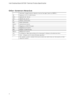
Intel Desktop Board DX79SI Technical Product Specification Other Common Notation # GB GB/s Gb/s KB Kbit kbits/s MB MB/s Mbit Mbits/s xxh x.x V * Used after a signal name to identify an active-low signal (such as USBP0#) Gigabyte (1,073,741,824 bytes) Gigabytes per second Gigabits per second - Intel DX79SI | Intel Desktop Board DX79SI Technical Product Specification - Page 7
13 1.1.3 Block Diagram 15 1.2 Legacy Considerations 16 1.3 Online Support 16 1.4 Processor 16 1.4.1 PCI Express x16 Graphics 17 1.5 System Memory 17 1.5.1 Memory Configurations 19 1.6 Intel® X79 Express Chipset 21 1.6.1 USB 21 1.6.2 SATA Interfaces 21 1.7 Real-Time Clock Subsystem 23 - Intel DX79SI | Intel Desktop Board DX79SI Technical Product Specification - Page 8
and Configuration 73 3.9.2 BIOS Boot Optimizations 73 3.10 BIOS Security Features 74 3.11 BIOS Performance Features 75 4 Error Messages and Beep Codes 4.1 Speaker 77 4.2 BIOS Beep Codes 77 4.3 Front-panel Power LED Blink Codes 78 4.4 BIOS Error Messages 78 4.5 Port 80h POST Codes 79 - Intel DX79SI | Intel Desktop Board DX79SI Technical Product Specification - Page 9
Pressing the Power Switch 32 7. Power States and Targeted System Power 33 8. Wake-up Devices and Events 34 9. Board Status LEDs 40 10. System Memory Map 45 11. Component-side Connectors and Headers Shown in Figure 13 49 12. Front Panel Audio Header for Intel HD Audio 50 13. Front Panel Audio - Intel DX79SI | Intel Desktop Board DX79SI Technical Product Specification - Page 10
32. BIOS Setup Program Function Keys 68 33. Acceptable Drives/Media Types for BIOS Recovery 71 34. Boot Device Menu Options 72 35. Supervisor and User Password Functions 74 36. BIOS Beep Codes 77 37. Front-panel Power LED Blink Codes 78 38. BIOS Error Messages 78 39. Port 80h POST Code Ranges - Intel DX79SI | Intel Desktop Board DX79SI Technical Product Specification - Page 11
3.0 Gb/s interfaces through the Intel X79 Express Chipset with Intel Rapid Storage Technology RAID support (black) • Two IEEE 1394a ports: ― One port via a back panel connector ― One port via a front-panel header (blue) • Separate module that provides both Bluetooth* and WiFi is included continued - Intel DX79SI | Intel Desktop Board DX79SI Technical Product Specification - Page 12
for PCI Express* Revision 3.0 • Suspend to RAM support • Wake on PCI, PCI Express, LAN, front panel, CIR, and USB ports LAN Support Dual-Gigabit (10/100/1000 Mbits/s) LAN subsystem using the Intel® 82579L and Intel® 82574L Gigabit Ethernet Controllers Expansion Capabilities • Two PCI Express - Intel DX79SI | Intel Desktop Board DX79SI Technical Product Specification - Page 13
Product Description 1.1.2 Board Layout Figure 1 shows the location of the major components on Intel Desktop Board DX79SI. Figure 1. Major Board Components Table 3 lists the components identified in Figure 1. 13 - Intel DX79SI | Intel Desktop Board DX79SI Technical Product Specification - Page 14
Remote thermal probe header Front chassis fan header 3.0 Gb/s SATA connectors (black) and 6.0 Gb/s SATA connectors (blue) Intel X79 Express Chipset Front panel USB 2.0 headers (4) Consumer IR emitter (output) header BIOS Setup configuration jumper block Power Fault LED Front panel USB 3.0 connector - Intel DX79SI | Intel Desktop Board DX79SI Technical Product Specification - Page 15
Product Description 1.1.3 Block Diagram Figure 2 is a block diagram of the major functional areas of the board. Figure 2. Block Diagram 15 - Intel DX79SI | Intel Desktop Board DX79SI Technical Product Specification - Page 16
for the Intel Desktop Board DX79SI Visit this World Wide Web site: http://www.intel.com/products/motherboard/index.htm http://www.intel.com/p/en_US/support?iid=hdr+support http://ark.intel.com Supported processors Chipset information BIOS and driver updates Tested memory Integration information - Intel DX79SI | Intel Desktop Board DX79SI Technical Product Specification - Page 17
Product Description 1.4.1 PCI Express x16 Graphics Intel Core i7 and Intel Xeon processors in an LGA2011 package support PCI Express add-in graphics cards via the board's PCI Express x16 connectors. These processors support the following generations of PCI Express: • PCI Express 3.0 with a raw bit - Intel DX79SI | Intel Desktop Board DX79SI Technical Product Specification - Page 18
V is the recommended and default setting for DDR3 memory voltage. The other memory voltage settings in the BIOS Setup program are provided for performance tuning purposes only. Altering the memory voltage may (i) reduce system stability and the useful life of the system, memory, and processor; (ii - Intel DX79SI | Intel Desktop Board DX79SI Technical Product Specification - Page 19
. Technology and device width can vary from one channel to the other. If different speed DIMMs are used between channels, the slowest memory timing will be used. For information about... Memory Configuration Examples Refer to: http://www.intel.com/support/motherboards/desktop/sb/cs011965.htm 19 - Intel DX79SI | Intel Desktop Board DX79SI Technical Product Specification - Page 20
Intel Desktop Board DX79SI Technical Product Specification Figure 3 illustrates the memory channel and DIMM configuration. Figure 3. Memory Channel and DIMM Configuration NOTE For best memory performance always install memory into the blue DIMM memory sockets if installing four DIMMs or less in your - Intel DX79SI | Intel Desktop Board DX79SI Technical Product Specification - Page 21
ports. The Intel X79 Express Chipset provides the USB controller for the 2.0 ports. The four USB 3.0 ports are provided by two NEC* UPD720200 controllers. The port arrangement is as follows: • Two USB 3.0 ports are implemented with stacked back panel connectors (blue) • Two USB 3.0 front panel ports - Intel DX79SI | Intel Desktop Board DX79SI Technical Product Specification - Page 22
order to use supported RAID features, you must first enable RAID in the BIOS. Also, during Microsoft Windows XP installation, you must press F6 to install the RAID drivers. See your Microsoft Windows XP documentation for more information about installing drivers during installation. Both Microsoft - Intel DX79SI | Intel Desktop Board DX79SI Technical Product Specification - Page 23
(CIR) headers • Serial IRQ interface compatible with serialized IRQ support for PCI systems • Intelligent power management, including a programmable wake-up event interface • PCI power management support The BIOS Setup program provides configuration options for the I/O controller. 1.8.1 Consumer - Intel DX79SI | Intel Desktop Board DX79SI Technical Product Specification - Page 24
Refer to Section 1.3, page 16 1.9.2 Audio Subsystem Components The audio subsystem includes the following components: • Intel X79 Express Chipset • Realtek ALC892 audio codec • Front panel audio header that supports Intel HD audio and AC '97 audio (a 2 x 5- pin header that provides mic in and line - Intel DX79SI | Intel Desktop Board DX79SI Technical Product Specification - Page 25
Audio Connectors NOTE The back panel audio line out connector is designed to power headphones or amplified speakers only. Poor audio quality occurs if passive (non-amplified) speakers are connected to this output. For information about The locations of the front panel audio header and S/PDIF audio - Intel DX79SI | Intel Desktop Board DX79SI Technical Product Specification - Page 26
Mbits/s) • Intel X79 Express Chipset • RJ-45 LAN connectors with integrated status LEDs Additional features of the LAN subsystem include: • CSMA/CD protocol engine • LAN connect interface between the PCH and the LAN controller • Conventional PCI bus power management ACPI technology support LAN - Intel DX79SI | Intel Desktop Board DX79SI Technical Product Specification - Page 27
drivers are available from Intel's World Wide Web site. For information about Obtaining LAN software and drivers Refer to http://downloadcenter.intel Connector LED Locations Table 6 describes the LED states when the board is powered up and the LAN subsystem is operating. Table 6. LAN Connector LED - Intel DX79SI | Intel Desktop Board DX79SI Technical Product Specification - Page 28
are available using the driver supplied with the motherboard. • CSR Bluetooth module (BC0401PC08) • Maximum data rate 3.0 Mb/s • Forward and backward compatibility with Bluetooth v1.1, v1.2, v2.0, and v2.1 • Integrated antenna • Operating system support (Windows XP, Windows Vista, and Windows 7 both - Intel DX79SI | Intel Desktop Board DX79SI Technical Product Specification - Page 29
The Bluetooth/WiFi Module enables the user to connect with a variety of WiFi enabled networks, access points and allows peer to peer connections. Driver support is provided by Microsoft operating systems like Microsoft Vista and Microsoft Windows 7 with additional support provided by the supplied - Intel DX79SI | Intel Desktop Board DX79SI Technical Product Specification - Page 30
monitoring can be implemented using Intel® Extreme Tuning Utility, Intel® Desktop Utility, or third-party software. For information about The functions of the fan headers Refer to Section 1.13.2.2, page 36 1.12.3 Chassis Intrusion and Detection The board supports a chassis security feature that - Intel DX79SI | Intel Desktop Board DX79SI Technical Product Specification - Page 31
locations of the thermal sensors and fan headers. Item A B C D E F G Description Rear chassis fan header Processor fan header Thermal diode, located on processor die Remote thermal probe header Front chassis fan header Intel X79 Express Chipset Auxiliary fan header Figure 7. Thermal Sensors and - Intel DX79SI | Intel Desktop Board DX79SI Technical Product Specification - Page 32
Soft-off feature that enables the operating system to power-off the computer (refer to the Advanced Configuration and Power Interface Specification at http://www.acpi.info/) • Support for multiple wake-up events (see Table 9 on page 34) • Support for a front panel power and sleep mode switch Table - Intel DX79SI | Intel Desktop Board DX79SI Technical Product Specification - Page 33
power to the system. Service can be performed safely. Notes: 1. Total system power is dependent on the system configuration, including add-in boards and peripherals powered by the system chassis' power supply. 2. Dependent on the standby power consumption of wake-up devices used in the system. 33 - Intel DX79SI | Intel Desktop Board DX79SI Technical Product Specification - Page 34
from S4 and S5 is recommended by Microsoft. 3. Wake from device/event not supported immediately upon return from AC loss. NOTE The use of these wake-up events from an ACPI state requires an operating system that provides full ACPI support. In addition, software, drivers, and peripherals must fully - Intel DX79SI | Intel Desktop Board DX79SI Technical Product Specification - Page 35
, the power supply removes all non-standby voltages. When resuming from an AC power failure, the computer returns to the power state it was in before power was interrupted (on or off). The computer's response can be set using the Last Power State feature in the BIOS Setup program's Boot menu. For - Intel DX79SI | Intel Desktop Board DX79SI Technical Product Specification - Page 36
control SIO • All fan headers support closed-loop fan control that can thermal monitoring Refer to Figure 13, page 48 Figure 7, page 31 1.13.2.3 LAN Wake Capabilities CAUTION For LAN wake capabilities, the +5 V standby line for the power supply power supply. LAN wake capabilities enable remote - Intel DX79SI | Intel Desktop Board DX79SI Technical Product Specification - Page 37
this specification can participate in power management and can be used to wake the computer. The use of Instantly Available PC technology requires operating system support and PCI 2.2 compliant add-in cards, PCI Express add-in cards, and drivers. 1.13.2.5 Wake from USB USB bus activity wakes the - Intel DX79SI | Intel Desktop Board DX79SI Technical Product Specification - Page 38
Intel Desktop Board DX79SI Technical Product Specification 1.13.2.10 Power Supervisor The Power Supervisor actively monitors the input voltages from the power supply and protects the board and any attached peripherals from electrical overstress and possible physical damage. The Power Supervisor will - Intel DX79SI | Intel Desktop Board DX79SI Technical Product Specification - Page 39
off. When the BIOS starts an activity such as memory initialization, the corresponding LED starts flashing. Once the activity has completed, the LED will remain on. Six additional LEDs can be used to monitor board functions such as hard drive activity, processor errors, and power faults. Refer to - Intel DX79SI | Intel Desktop Board DX79SI Technical Product Specification - Page 40
Green Initialization F Memory Green Initialization G CPU Initialization Green H Hard Drive Blue Activity I CPU Hot Red J VR Hot Red K Watch Dog Red Fire/Back to BIOS L +5 V standby Green power indicator M CPU Error Red N Power Fault LED Red Supported Modes On/Off - Intel DX79SI | Intel Desktop Board DX79SI Technical Product Specification - Page 41
the same behavior as the front panel power button connected via the front panel header. The onboard power button does NOT remove standby power. This button is intended for use at integration facilities for testing purposes. The power button on the front panel is recommended for all other instances - Intel DX79SI | Intel Desktop Board DX79SI Technical Product Specification - Page 42
Intel Desktop Board DX79SI Technical Product Specification 42 - Intel DX79SI | Intel Desktop Board DX79SI Technical Product Specification - Page 43
PCI bus add-in cards, PCI Express configuration space, BIOS (SPI Flash device), and chipset overhead resides above the top of DRAM (total system memory). On a system that has 64 GB of system memory installed, it is not possible to use all of the installed memory due to system address space being - Intel DX79SI | Intel Desktop Board DX79SI Technical Product Specification - Page 44
Intel Desktop Board DX79SI Technical Product Specification Figure 10. Detailed System Memory Address Map 44 - Intel DX79SI | Intel Desktop Board DX79SI Technical Product Specification - Page 45
on video adapter used. Video memory and BIOS Extended BIOS data (movable by memory manager software) Extended conventional memory Conventional memory 2.2 Connectors and Headers CAUTION Only the following connectors and headers have overcurrent protection: back panel and front panel USB, as well as - Intel DX79SI | Intel Desktop Board DX79SI Technical Product Specification - Page 46
Intel Desktop Board DX79SI Technical Product Specification 2.2.1 Back Panel Connectors Figure 11 shows the location of the back panel connectors for the board. Item A B C D E F G H I J K L M N Description Back to BIOS button USB 3.0 ports LAN connector USB 2.0 ports IEEE 1394a connector USB 2.0 - Intel DX79SI | Intel Desktop Board DX79SI Technical Product Specification - Page 47
Technical Reference 2.2.1.1 I/O Shield The I/O shield provided with the board allows access to all back panel connectors and is compatible with standard mini-ITX and ATX chassis. Figure 12 shows an I/O shield reference diagram. Figure 12. I/O Shield Reference Diagram 47 - Intel DX79SI | Intel Desktop Board DX79SI Technical Product Specification - Page 48
Intel Desktop Board DX79SI Technical Product Specification 2.2.2 Component-side Connectors and Headers Figure 13 shows the locations of the component-side connectors and headers. Figure 13. Component-side Connectors - Intel DX79SI | Intel Desktop Board DX79SI Technical Product Specification - Page 49
V processor core voltage connector (2 x 4 pin) L Main power connector (2 x 12 pin) M Remote thermal probe header N Rear chassis fan header O 3.0 Gb/s SATA connectors (black) and 6.0 Gb/s SATA connectors (blue) P Front panel USB 2.0 header Q Front panel USB 2.0 header R Front panel USB - Intel DX79SI | Intel Desktop Board DX79SI Technical Product Specification - Page 50
3 MIC_BIAS Front panel microphone input signal (biased when supporting stereo microphone) Ground used by analog audio circuits Microphone power/additional MIC input for stereo microphone support 4 PRESENCE# 5 FP_OUT_R 6 AUD_GND Active low signal that signals BIOS that an Intel HD Audio - Intel DX79SI | Intel Desktop Board DX79SI Technical Product Specification - Page 51
RXN 6 RXP 7 Ground Table 17. S/PDIF Header Pin Signal Name 1 Ground 2 S/PDIF out 3 Key (no pin) 4 +5 VDC Table 18. USB 2.0 Headers Pin Signal Name 1 +5 V DC 2 D− 3 D+ 4 Ground 5 Key (no pin) Technical Reference Pin 2 4 6 8 10 Signal Name Data A (negative) Ground Data - Intel DX79SI | Intel Desktop Board DX79SI Technical Product Specification - Page 52
Intel Desktop Board DX79SI Technical Product Specification Table 19. USB 3.0 Connector Pin Signal Name 1 Vbus 2 IntA_P1_SSRX− 3 ICC Port2 SuperSpeed Rx+ Power Table 20. Chassis Intrusion Header Pin Signal Name 1 Intruder# 2 Ground Table 21. Processor, Front and Rear Chassis, and - Intel DX79SI | Intel Desktop Board DX79SI Technical Product Specification - Page 53
out 1 2 Emitter out 2 3 Ground 4 Key (no pin) 5 Jack detect 1 6 Jack detect 2 Table 21. Front Panel CIR Receiver (Input) Header Pin Signal Name 1 Ground 2 LED 3 NC 4 Learn-in 5 5 V standby 6 VCC 7 Key (no pin) 8 CIR Input 2.2.2.2 Add-in Card Connectors The board has the - Intel DX79SI | Intel Desktop Board DX79SI Technical Product Specification - Page 54
Intel Desktop Board DX79SI Technical Product Specification 2.2.2.3 Power Supply Connectors The board has the following power supply connectors: • Main power - a 2 x 12 connector. This connector is compatible with 2 x 10 connectors previously used on Intel Desktop boards. The board supports the use - Intel DX79SI | Intel Desktop Board DX79SI Technical Product Specification - Page 55
Out On/Off Switch 6 FPBUT_IN In 8 Ground Not Connected 10 N/C Description Front panel green LED Front panel yellow LED Power switch Ground Not connected Figure 14. Connection Diagram for Front Panel Header 2.2.2.4.1 Hard Drive Activity LED Header Pins 1 and 3 can be connected - Intel DX79SI | Intel Desktop Board DX79SI Technical Product Specification - Page 56
colors only. Actual LED colors are chassis-specific. 2.2.2.4.4 Power Switch Header Pins 6 and 8 can be connected to a front panel momentary-contact power switch. The switch must pull the SW_ON# pin to ground for at least 50 ms to signal the power supply to switch on or off. (The time requirement - Intel DX79SI | Intel Desktop Board DX79SI Technical Product Specification - Page 57
Technical Reference 2.2.2.5 Front Panel USB 2.0 Headers Figure 15 is a connection diagram for the front panel USB 2.0 headers. NOTE • The +5 V DC power on the headers is fused. • Use only a front panel USB 2.0 connector that conforms to the USB 2.0 specification for high-speed USB devices. Figure 15 - Intel DX79SI | Intel Desktop Board DX79SI Technical Product Specification - Page 58
The 3-pin jumper block determines the BIOS Setup program's mode. Table 27 describes the jumper settings for the three modes: normal, configure, and recovery. When the jumper is set to configure mode and the computer is powered-up, the BIOS compares the processor version and the microcode version in - Intel DX79SI | Intel Desktop Board DX79SI Technical Product Specification - Page 59
Technical Reference Table 27. BIOS Setup Configuration Jumper Settings Function/Mode Normal Configure Jumper Setting 1-2 2-3 Configuration The BIOS uses current configuration information and passwords for booting. After the POST runs, Setup runs automatically. The maintenance menu is displayed. - Intel DX79SI | Intel Desktop Board DX79SI Technical Product Specification - Page 60
Intel Desktop Board DX79SI Technical Product Specification 2.4 Mechanical Considerations 2.4.1 Form Factor The Dimensions are given in inches [millimeters]. The outer dimensions are 12.00 inches by 9.60 inches [304.80 millimeters by 243.84 millimeters]. Location of the I/O connectors and mounting - Intel DX79SI | Intel Desktop Board DX79SI Technical Product Specification - Page 61
For example, for a system consisting of a supported 130 W processor (see section 1.4 on page 16 for a list of supported processors), 8 GB DDR3 RAM, one high end video card, one hard disk drive, one optical drive, and all board peripherals enabled, the minimum recommended power supply is 460 W. Table - Intel DX79SI | Intel Desktop Board DX79SI Technical Product Specification - Page 62
Intel Desktop Board DX79SI Technical Product Specification 2.5.2 Fan Header Current Capability CAUTION The processor fan must be connected to the processor fan header, not to a chassis fan header. Connecting the processor exceed the system's power supply +5 V maximum current or 14 A in total. 62 - Intel DX79SI | Intel Desktop Board DX79SI Technical Product Specification - Page 63
temperature of 38 oC at the processor fan inlet is a requirement. Use a processor heat sink that provides omni-directional airflow to maintain required airflow across the processor voltage regulator area. If a non omni-directional thermal solution is used customer might need to provide supplemental - Intel DX79SI | Intel Desktop Board DX79SI Technical Product Specification - Page 64
proper airflow to cool the board. Table 30. Thermal Considerations for Components Component Maximum Case Temperature Processor For processor case temperature, see processor datasheets and processor specification updates Intel X79 Express Chipset 104 oC (under bias) For information about - Intel DX79SI | Intel Desktop Board DX79SI Technical Product Specification - Page 65
random failure rates. The calculation is based on the Telcordia SR-332, Method I Case 1 50% electrical stress, 55 ºC ambient. The MTBF prediction is used to estimate repair rates and spare parts requirements. The MTBF data is calculated from predicted data at 55 ºC. The MTBF for the board is 134, - Intel DX79SI | Intel Desktop Board DX79SI Technical Product Specification - Page 66
Intel Desktop Board DX79SI Technical Product Specification 66 - Intel DX79SI | Intel Desktop Board DX79SI Technical Product Specification - Page 67
Setup program can be used to view and change the BIOS settings for the computer. The BIOS Setup program is accessed by pressing the key after the Power-On Self-Test (POST) memory test begins and before the operating system boot begins. The menu bar is shown below. Maintenance Main Configuration - Intel DX79SI | Intel Desktop Board DX79SI Technical Product Specification - Page 68
and Processor overrides Sets passwords and security features Power Configures power management features and power supply controls Boot Selects boot options Exit Saves or discards changes to Setup program options Table 33 lists the function keys available for menu screens. Table 33. BIOS Setup - Intel DX79SI | Intel Desktop Board DX79SI Technical Product Specification - Page 69
when the operating system's USB drivers are not yet available. Legacy USB support is used to access the BIOS Setup program, and to install an operating system that supports USB. By default, Legacy USB support is set to Enabled. Legacy USB support operates as follows: 1. When you apply power to the - Intel DX79SI | Intel Desktop Board DX79SI Technical Product Specification - Page 70
Intel Desktop Board DX79SI Technical Product Specification To install an operating system that supports USB, verify that Legacy USB support in the BIOS Setup program is set to Enabled and follow the operating system's installation instructions. 3.6 BIOS Updates The BIOS can be updated using either - Intel DX79SI | Intel Desktop Board DX79SI Technical Product Specification - Page 71
used for BIOS recovery? Optical drive connected to the SATA interface Yes USB removable drive (a USB Flash Drive, for example) Yes USB diskette drive (with a 1.44 MB diskette) No USB hard disk drive No For information about BIOS recovery Refer to http://www.intel.com/support/motherboards - Intel DX79SI | Intel Desktop Board DX79SI Technical Product Specification - Page 72
add-in card with a remote boot ROM installed. Pressing the key during POST automatically forces booting from the LAN. To use this key during POST, the User Access Level in the BIOS Setup program's Security menu must be set to Full. 3.8.3 Booting Without Attached Devices For use in embedded - Intel DX79SI | Intel Desktop Board DX79SI Technical Product Specification - Page 73
used. This can reduce up to four seconds of option ROM boot time. • The BIOS will automatically not load the option ROM for the SATA controller if no drives are installed in it during POST. NOTE It is possible to optimize the boot process to the point where the system boots so quickly that the Intel - Intel DX79SI | Intel Desktop Board DX79SI Technical Product Specification - Page 74
Intel Desktop Board DX79SI Technical Product Specification 3.10 BIOS Security Features The BIOS includes security features that restrict access to the BIOS Setup program and who can boot the computer. A supervisor password and a user password can be set for the BIOS Setup program and for booting - Intel DX79SI | Intel Desktop Board DX79SI Technical Product Specification - Page 75
3.11 BIOS Performance Features The BIOS includes the following options to provide custom performance enhancements when using an Intel Core i7 and Intel Xeon processor in an LGA2011 socket. • Processor frequency adjustment • Processor voltage adjustment • Memory clock adjustments • Memory voltage - Intel DX79SI | Intel Desktop Board DX79SI Technical Product Specification - Page 76
Intel Desktop Board DX79SI Technical Product Specification 76 - Intel DX79SI | Intel Desktop Board DX79SI Technical Product Specification - Page 77
during POST, the BIOS causes the board's speaker to beep an error message describing the problem (see Table 37). Table 37. BIOS Beep Codes Type Pattern F2 Setup/F10 Boot Menu One 0.5 second beep when BIOS is ready to Prompt accept keyboard input BIOS update in progress None Video error On - Intel DX79SI | Intel Desktop Board DX79SI Technical Product Specification - Page 78
Power LED Blink Codes Whenever a recoverable error occurs during POST, the BIOS causes the board's front panel power LED to blink an error message describing the problem (see Table 38). Table 38. Front-panel Power LED Blink Codes Type Pattern F2 Setup/F10 Boot Menu None Prompt BIOS update - Intel DX79SI | Intel Desktop Board DX79SI Technical Product Specification - Page 79
Error Messages and Beep Codes 4.5 Port 80h POST Codes During the POST, the BIOS generates diagnostic progress codes (POST codes) to I/O port 80h. If the POST fails, execution stops and the last POST code generated is left at port 80h. This code is useful for determining the point where an error - Intel DX79SI | Intel Desktop Board DX79SI Technical Product Specification - Page 80
Intel Desktop Board DX79SI Technical Product Specification Table 41. Port 80h POST Codes Port 80 Code Progress Code Enumeration 0x00,0x01,0x02,0x03,0x04,0x05 0x10,0x20,0x30,0x40,0x50 0x08 0x09 ACPI S States Entering S0, S2, S3, S4, or S5 state Resuming from S2, S3, S4, S5 Security Phase (SEC) - Intel DX79SI | Intel Desktop Board DX79SI Technical Product Specification - Page 81
Error Messages and Beep Codes Table 41. Port 80h POST Codes (continued) Port 80 Code Progress Code Enumeration PEIMs/Recovery 0x31 Crisis Recovery has initiated 0x33 Loading recovery capsule 0x34 Start recovery capsule/ valid capsule is found CPU Initialization CPU PEI Phase 0x41 0x42 - Intel DX79SI | Intel Desktop Board DX79SI Technical Product Specification - Page 82
Intel Desktop Board DX79SI Technical Product Specification Table 41. Port 80h POST Codes (continued) Port 80 Code 0x60 0x61 0x62 0x63 0x64 0x65 0x66 0x67 0x68 0x69 0x6A 0x6B 0x6C 0x6D 0x6E 0x6F 0x90 0x91 0x92 0x93 0x94 0x95 0x98 0x99 0x9A 0x9B 0xB0 0xB1 Progress Code Enumeration BDS BDS driver - Intel DX79SI | Intel Desktop Board DX79SI Technical Product Specification - Page 83
Error Messages and Beep Codes Table 41. Port 80h POST Codes (continued) Port 80 Code Progress Code Enumeration Removable Media 0xB8 Resetting removable media 0xB9 Disabling removable media 0xBA 0xBB Detecting presence of a removable media (IDE, CDROM detection etc.) Enabling/configuring a - Intel DX79SI | Intel Desktop Board DX79SI Technical Product Specification - Page 84
Intel Desktop Board DX79SI Technical Product Specification Table 42. Typical Port 80h POST Sequence POST Code 21 22 Description Initializing a chipset component Reading SPD from memory DIMMs 23 Detecting presence of memory DIMMs 25 Configuring memory 28 Testing memory 34 Loading recovery - Intel DX79SI | Intel Desktop Board DX79SI Technical Product Specification - Page 85
(EMC) standards • Product certification markings 5.1.1 Safety Standards Intel Desktop Board DX79SI complies with the safety standards stated in Table 43 when correctly installed in a compatible host system. Table 43. Safety Standards Standard Title CSA/UL 60950-1 EN 60950-1 IEC 60950 - Intel DX79SI | Intel Desktop Board DX79SI Technical Product Specification - Page 86
Technical Product Specification 5.1.2 European Union Declaration of Conformity Statement We, Intel Corporation, declare under our sole responsibility that the product Intel® Desktop Board DX79SI is in conformity with all applicable essential requirements necessary for CE marking, following the - Intel DX79SI | Intel Desktop Board DX79SI Technical Product Specification - Page 87
branded products to return used products to selected locations for proper recycling. Please consult the http://www.intel.com/intel/other/ehs/product_ecology for the details of this program, including the scope of covered products, available locations, shipping instructions, terms and conditions, etc - Intel DX79SI | Intel Desktop Board DX79SI Technical Product Specification - Page 88
pour en savoir plus sur ce programme, à savoir les produits concernés, les adresses disponibles, les instructions d'expédition, les conditions générales, etc http://www.intel.com/in tel/other/ehs/product_ecology Malay Sebagai sebahagian daripada komitmennya terhadap tanggungjawab persekitaran - Intel DX79SI | Intel Desktop Board DX79SI Technical Product Specification - Page 89
ına gidin. 5.1.4 EMC Regulations Intel Desktop Board DX79SI complies with the EMC regulations stated in Table 44 when correctly installed in a compatible host system. Table 44. EMC Regulations Regulation FCC 47 CFR Part 15, Subpart B Title Title 47 of the Code of Federal Regulations, Part 15 - Intel DX79SI | Intel Desktop Board DX79SI Technical Product Specification - Page 90
Intel Desktop Board DX79SI Technical Product Specification FCC Declaration of Conformity This device complies with Part 15 a residential installation. This equipment generates, uses, and can radiate radio frequency energy and, if not installed and used in accordance with the instructions, may cause - Intel DX79SI | Intel Desktop Board DX79SI Technical Product Specification - Page 91
receiver in a domestic environment, it may cause radio interference. Install and use the equipment according to the instruction manual. Korea Class B Statement Korea Class B Statement translation: This equipment is for home use, and has acquired electromagnetic conformity registration, so it can be - Intel DX79SI | Intel Desktop Board DX79SI Technical Product Specification - Page 92
governmental agencies in the definition of new requirements. Intel Desktop Board DX79SI meets the following program requirements in an adequate system configuration, including appropriate selection of an efficient power supply: • Energy Star v5.0, category B • EPEAT* • Korea e-Standby • European - Intel DX79SI | Intel Desktop Board DX79SI Technical Product Specification - Page 93
RSM) C-tick mark. Includes adjacent Intel supplier code number, N-232. Japan VCCI ( CPU-DX79SI. Taiwan BSMI (Bureau of Standards, Metrology and Inspections) mark. Includes adjacent Intel RoHS/Environmentally Friendly Use Period Logo: This is an example of the symbol used on Intel Desktop Boards and - Intel DX79SI | Intel Desktop Board DX79SI Technical Product Specification - Page 94
Intel Desktop Board DX79SI Technical Product Specification 5.2 Battery Disposal Information CAUTION Risk of explosion if the battery is replaced with an incorrect type. Batteries should be recycled where possible. Disposal of used batteries must be in accordance with local environmental regulations. - Intel DX79SI | Intel Desktop Board DX79SI Technical Product Specification - Page 95
Regulatory Compliance and Battery Disposal Information PRECAUCIÓN Existe peligro de explosión si la pila no se cambia de forma adecuada. Utilice solamente pilas iguales o del mismo tipo que las recomendadas por el fabricante del equipo. Para deshacerse de las pilas usadas, siga igualmente las - Intel DX79SI | Intel Desktop Board DX79SI Technical Product Specification - Page 96
Intel Desktop Board DX79SI Technical Product Specification AWAS Risiko letupan wujud jika bateri digantikan dengan jenis yang tidak betul. Bateri sepatutnya dikitar semula jika boleh. Pelupusan bateri terpakai mestilah - Intel DX79SI | Intel Desktop Board DX79SI Technical Product Specification - Page 97
Regulatory Compliance and Battery Disposal Information 97 - Intel DX79SI | Intel Desktop Board DX79SI Technical Product Specification - Page 98
Intel Desktop Board DX79SI Technical Product Specification 98
-
 1
1 -
 2
2 -
 3
3 -
 4
4 -
 5
5 -
 6
6 -
 7
7 -
8
-
9
-
10
-
11
-
12
-
13
-
14
-
15
-
16
-
17
-
18
-
19
-
20
-
21
-
22
-
23
-
24
-
25
-
26
-
27
-
28
-
29
-
30
-
31
-
32
-
33
-
34
-
35
-
36
-
37
-
38
-
39
-
40
-
41
-
42
-
43
-
44
-
45
-
46
-
47
-
48
-
49
-
50
-
51
-
52
-
53
-
54
-
55
-
56
-
57
-
58
-
59
-
60
-
61
-
62
-
63
-
64
-
65
-
66
-
67
-
68
-
69
-
70
-
71
-
72
-
73
-
74
-
75
-
76
-
77
-
78
-
79
-
80
-
81
-
82
-
83
-
84
-
85
-
86
-
87
-
88
-
89
-
90
-
91
-
92
-
93
-
94
-
95
-
96
-
97
-
98
 |
 |

Intel® Desktop Board
DX79SI
Technical Product Specification
June 2012
Order Number:
G31801-004
The Intel
®
Desktop Board DX79SI may contain design defects or errors known as errata that may cause the product to deviate from published specifications.
Current characterized errata are documented in the Intel Desktop Board DX79SI Specification Update.