Intel DX79SI Intel Desktop Board DX79SI Technical Product Specification - Page 21
Intel, X79 Express Chipset
 |
View all Intel DX79SI manuals
Add to My Manuals
Save this manual to your list of manuals |
Page 21 highlights
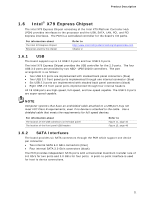
Product Description 1.6 Intel® X79 Express Chipset The Intel X79 Express Chipset consisting of the Intel X79 Platform Controller Hub (PCH) provides interfaces to the processor and the USB, SATA, LAN, PCI, and PCI Express interfaces. The PCH is a centralized controller for the board's I/O paths. For information about The Intel X79 Express Chipset Resources used by the chipset Refer to http://www.intel.com/products/desktop/chipsets/index.htm Chapter 2 1.6.1 USB The board supports up to 14 USB 2.0 ports and four USB 3.0 ports. The Intel X79 Express Chipset provides the USB controller for the 2.0 ports. The four USB 3.0 ports are provided by two NEC* UPD720200 controllers. The port arrangement is as follows: • Two USB 3.0 ports are implemented with stacked back panel connectors (blue) • Two USB 3.0 front panel ports implemented through one internal connector (blue) • Six USB 2.0 ports are implemented with stacked back panel connectors (black) • Eight USB 2.0 front panel ports implemented through four internal headers All 18 USB ports are high-speed, full-speed, and low-speed capable. The USB 3.0 ports are super-speed capable. NOTE Computer systems that have an unshielded cable attached to a USB port may not meet FCC Class B requirements, even if no device is attached to the cable. Use a shielded cable that meets the requirements for full-speed devices. For information about The location of the USB connectors on the back panel The location of the front panel USB headers Refer to Figure 11, page 46 Figure 13, page 48 1.6.2 SATA Interfaces The board provides six SATA connectors through the PCH which support one device per connector: • Two internal SATA 6.0 Gb/s connectors (blue) • Four internal SATA 3.0 Gb/s connectors (black) The PCH provides independent SATA ports with a theoretical maximum transfer rate of 6.0 Gb/s for two ports and 3.0 Gb/s for four ports. A point-to-point interface is used for host to device connections. 21
-
 1
1 -
2
-
3
-
4
-
5
-
6
-
7
-
8
-
9
-
10
-
11
-
12
-
13
-
14
-
15
-
 16
16 -
 17
17 -
 18
18 -
 19
19 -
 20
20 -
 21
21 -
 22
22 -
 23
23 -
 24
24 -
 25
25 -
 26
26 -
27
-
28
-
29
-
30
-
31
-
32
-
33
-
34
-
35
-
36
-
37
-
38
-
39
-
40
-
41
-
42
-
43
-
44
-
45
-
46
-
47
-
48
-
49
-
50
-
51
-
52
-
53
-
54
-
55
-
56
-
57
-
58
-
59
-
60
-
61
-
62
-
63
-
64
-
65
-
66
-
67
-
68
-
69
-
70
-
71
-
72
-
73
-
74
-
75
-
76
-
77
-
78
-
79
-
80
-
81
-
82
-
83
-
84
-
85
-
86
-
87
-
88
-
89
-
90
-
91
-
92
-
93
-
94
-
95
-
96
-
97
-
98
 |
 |