Intel DX79SI Intel Desktop Board DX79SI Technical Product Specification - Page 52
Table 19., USB 3.0 Connector, Table 20., Chassis Intrusion Header, Table 21., Processor, Front
 |
View all Intel DX79SI manuals
Add to My Manuals
Save this manual to your list of manuals |
Page 52 highlights
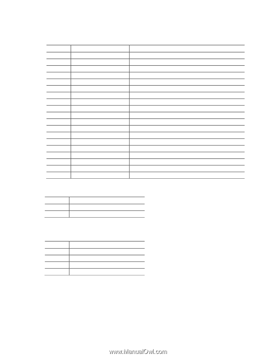
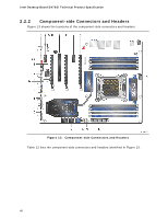
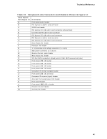
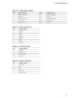
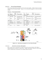
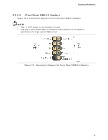
Intel Desktop Board DX79SI Technical Product Specification Table 19. USB 3.0 Connector Pin Signal Name 1 Vbus 2 IntA_P1_SSRX− 3 IntA_P1_SSRX+ 4 GND 5 IntA_P1_SSTX− 6 IntA_P1_SSTX+ 7 GND 8 IntA_P1_D− 9 IntA_P1_D+ 10 ID 11 IntA_P2_D+ 12 IntA_P2_D− 13 GND 14 IntA_P2_SSTX+ 15 IntA_P2_SSTX− 16 GND 17 IntA_P2_SSRX+ 18 IntA_P2_SSRX− 19 Vbus Description Power USB3 ICC Port1 SuperSpeed Rx− USB3 ICC Port1 SuperSpeed Rx+ Ground USB3 ICC Port1 SuperSpeed Tx− USB3 ICC Port1 SuperSpeed Tx+ Ground USB3 ICC Port1 D− (USB2 Signal D−) USB3 ICC Port1 D+ (USB2 Signal D+) Over Current Protection USB3 ICC Port2 D+ (USB2 Signal D+) USB3 ICC Port2 D− (USB2 Signal D−) Ground USB3 ICC Port2 SuperSpeed Tx+ USB3 ICC Port2 SuperSpeed Tx− Ground USB3 ICC Port2 SuperSpeed Rx+ USB3 ICC Port2 SuperSpeed Rx+ Power Table 20. Chassis Intrusion Header Pin Signal Name 1 Intruder# 2 Ground Table 21. Processor, Front and Rear Chassis, and Auxiliary (4-Pin) Fan Headers Pin Signal Name 1 Ground (Note) 2 +12 V 3 FAN_TACH 4 FAN_CONTROL Note: These fan headers use Pulse Width Modulation control for fan speed. 52
-
 1
1 -
2
-
3
-
4
-
5
-
6
-
7
-
8
-
9
-
10
-
11
-
12
-
13
-
14
-
15
-
16
-
17
-
18
-
19
-
20
-
21
-
22
-
23
-
24
-
25
-
26
-
27
-
28
-
29
-
30
-
31
-
32
-
33
-
34
-
35
-
36
-
37
-
38
-
39
-
40
-
41
-
42
-
43
-
44
-
45
-
46
-
 47
47 -
 48
48 -
 49
49 -
 50
50 -
 51
51 -
 52
52 -
 53
53 -
 54
54 -
 55
55 -
 56
56 -
 57
57 -
58
-
59
-
60
-
61
-
62
-
63
-
64
-
65
-
66
-
67
-
68
-
69
-
70
-
71
-
72
-
73
-
74
-
75
-
76
-
77
-
78
-
79
-
80
-
81
-
82
-
83
-
84
-
85
-
86
-
87
-
88
-
89
-
90
-
91
-
92
-
93
-
94
-
95
-
96
-
97
-
98
 |
 |