Intel DX79SI Intel Desktop Board DX79SI Technical Product Specification - Page 50
Signal Tables for the Connectors and Headers - bios key
 |
View all Intel DX79SI manuals
Add to My Manuals
Save this manual to your list of manuals |
Page 50 highlights
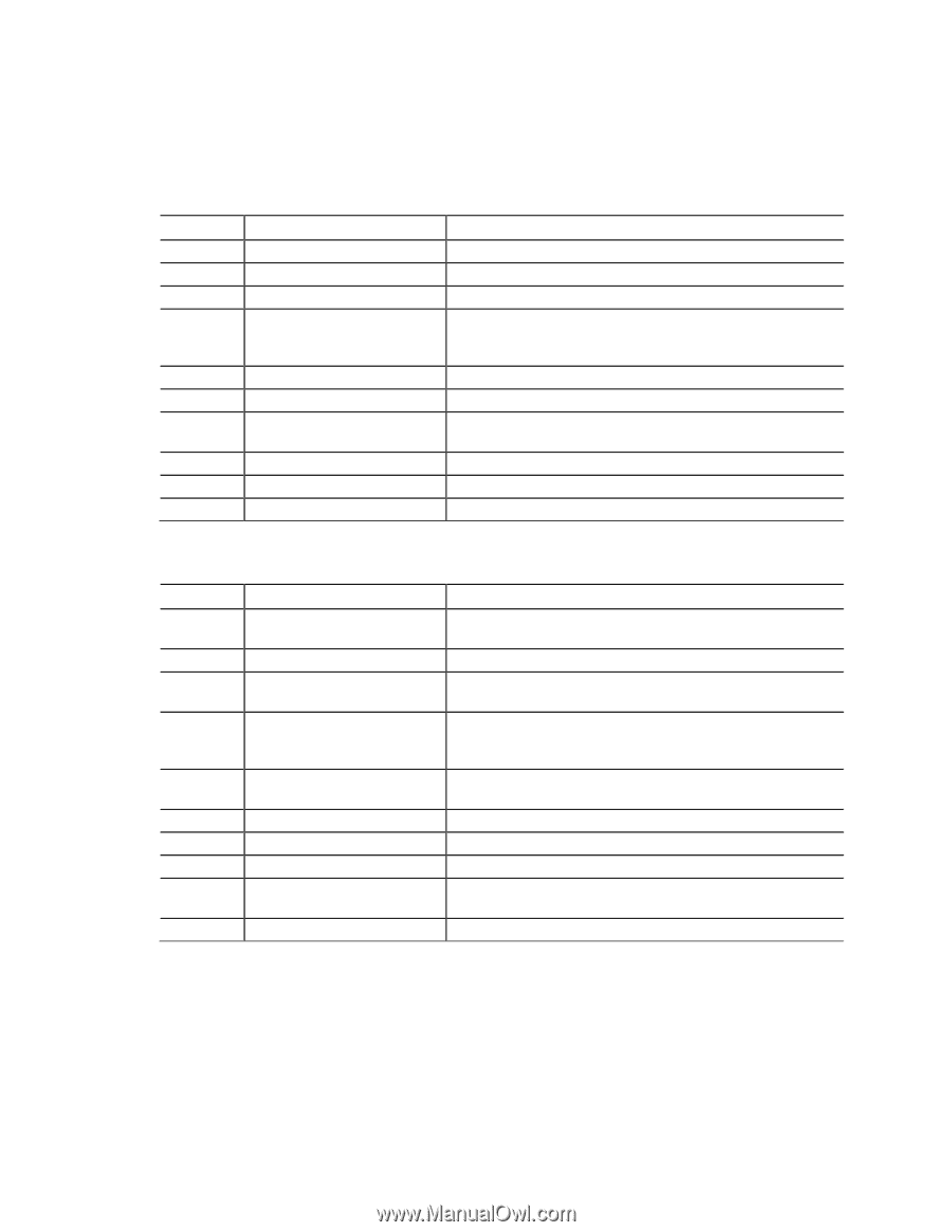
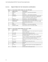
Intel Desktop Board DX79SI Technical Product Specification 2.2.2.1 Signal Tables for the Connectors and Headers Table 13. Front Panel Audio Header for Intel HD Audio Pin Signal Name Description 1 PORT_1L Analog Port 1 - left channel (microphone) 2 GND Ground 3 PORT_1R Analog Port 1 - right channel (microphone) 4 PRESENCE# Active low signal that signals BIOS that an Intel HD Audio dongle is connected to the analog header. PRESENCE#=0 when an Intel HD Audio dongle is connected 5 PORT_2R Analog Port 2 - right channel (headphone) 6 SENSE1_RETURN Jack detection return for front panel (JACK1) 7 SENSE_SEND Jack detection sense line from the Intel HD Audio CODEC jack detection resistor network 8 KEY No pin 9 PORT_2L Analog Port 2 - left channel (headphone) 10 SENSE2_RETURN Jack detection return for front panel (JACK2) Table 14. Front Panel Audio Header for AC '97 Audio Pin Signal Name Description 1 MIC 2 AUD_GND 3 MIC_BIAS Front panel microphone input signal (biased when supporting stereo microphone) Ground used by analog audio circuits Microphone power/additional MIC input for stereo microphone support 4 PRESENCE# 5 FP_OUT_R 6 AUD_GND Active low signal that signals BIOS that an Intel HD Audio dongle is connected to the analog header. PRESENCE#=0 when an Intel HD Audio dongle is connected. Right channel audio signal to front panel (headphone drive capable) Ground used by analog audio circuits 7 RESERVED 8 KEY 9 FP_OUT_L 10 AUD_GND Reserved No pin Left channel audio signal to front panel (headphone drive capable) Ground used by analog audio circuits 50
-
 1
1 -
2
-
3
-
4
-
5
-
6
-
7
-
8
-
9
-
10
-
11
-
12
-
13
-
14
-
15
-
16
-
17
-
18
-
19
-
20
-
21
-
22
-
23
-
24
-
25
-
26
-
27
-
28
-
29
-
30
-
31
-
32
-
33
-
34
-
35
-
36
-
37
-
38
-
39
-
40
-
41
-
42
-
43
-
44
-
 45
45 -
 46
46 -
 47
47 -
 48
48 -
 49
49 -
 50
50 -
 51
51 -
 52
52 -
 53
53 -
 54
54 -
 55
55 -
56
-
57
-
58
-
59
-
60
-
61
-
62
-
63
-
64
-
65
-
66
-
67
-
68
-
69
-
70
-
71
-
72
-
73
-
74
-
75
-
76
-
77
-
78
-
79
-
80
-
81
-
82
-
83
-
84
-
85
-
86
-
87
-
88
-
89
-
90
-
91
-
92
-
93
-
94
-
95
-
96
-
97
-
98
 |
 |