Intel DX79SI Product Guide for Intel Desktop Board DX79SI - Page 37
Installing a Processor
 |
View all Intel DX79SI manuals
Add to My Manuals
Save this manual to your list of manuals |
Page 37 highlights
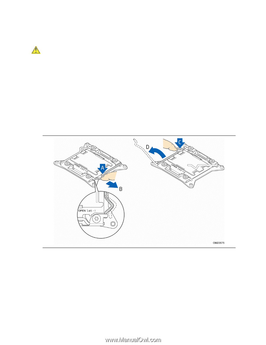
Installing and Replacing Desktop Board Components Installing a Processor CAUTION Before installing or removing a processor, make sure the AC power has been removed by unplugging the power cord from the computer; the standby power LED should not be lit (see Figure 5 on page 25). Failure to do so could damage the processor and the board. To install a processor, follow these instructions: 1. Observe the precautions in "Before You Begin" on page 33. 2. Open the socket lever marked "OPEN 1st" by pushing the lever down and away from the socket (Figure 12, A and B). Do not force the lever up to the fully open position. 3. Open the socket lever marked "CLOSE 1st" by pushing the lever down and away from the socket (Figure 12, C and D). Rotate the socket lever to its fully open position as shown Figure 12. Unlatch the Socket Levers 37
-
 1
1 -
2
-
3
-
4
-
5
-
6
-
7
-
8
-
9
-
10
-
11
-
12
-
13
-
14
-
15
-
16
-
17
-
18
-
19
-
20
-
21
-
22
-
23
-
24
-
25
-
26
-
27
-
28
-
29
-
30
-
31
-
 32
32 -
 33
33 -
 34
34 -
 35
35 -
 36
36 -
 37
37 -
 38
38 -
 39
39 -
 40
40 -
 41
41 -
 42
42 -
43
-
44
-
45
-
46
-
47
-
48
-
49
-
50
-
51
-
52
-
53
-
54
-
55
-
56
-
57
-
58
-
59
-
60
-
61
-
62
-
63
-
64
-
65
-
66
-
67
-
68
-
69
-
70
-
71
-
72
-
73
-
74
-
75
-
76
-
77
-
78
-
79
-
80
-
81
-
82
-
83
-
84
-
85
-
86
-
87
-
88
-
89
-
90
 |
 |