Intel E6420 Design Guidelines - Page 112
E.2.1.1, Temperature to begin fan acceleration
 |
UPC - 735858192569
View all Intel E6420 manuals
Add to My Manuals
Save this manual to your list of manuals |
Page 112 highlights
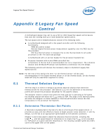
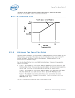
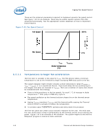
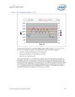
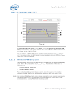
Legacy Fan Speed Control These are the minimum parameters required to implement acoustic fan speed control. See Figure 7-40 for an example. There may be vendor specific options that offer enhanced functionality. See the appropriate vendor datasheet on how to implement those features. Figure 7-40. Fan Speed Control Full Speed 100 % Min Speed X % TLOW TCONTROL Diode Temperature (°C) E.2.1.1 Temperature to begin fan acceleration The first item to consider is the value for TLOW. The FSC device needs a minimum temperature to set as the threshold to begin increasing PWM duty cycle to the fan. The system designer might initially consider a small temperature range (TCONTROL - TLOW = TRANGE), 5 °C to accelerate the fan. That would delay the fan accelerating for the longest time after an increase in TSENSOR. There are a number of issues that should be considered with this strategy There is little granularity in the fan speeds. For each 1 °C of increase in diode temperature = 20% jump in PWM duty cycle % Fan speed oscillation as the thermal solution chases the on-die thermal sensor temperature Having TSENSOR overshoot TCONTROL and the thermal profile causing the Thermal Control Circuit to activate to reduce the temperature. In extreme cases THERMTRIP# activates and shuts down the processor The first two cases can create a poor acoustic response for the user. The third case the user could notice a drop in performance as the thermal control circuit reduces the power. Figure 7-41 is an example of this situation. The system begins at idle and the Maxpower program is started at 65% workload. 112 Thermal and Mechanical Design Guidelines
-
 1
1 -
2
-
3
-
4
-
5
-
6
-
7
-
8
-
9
-
10
-
11
-
12
-
13
-
14
-
15
-
16
-
17
-
18
-
19
-
20
-
21
-
22
-
23
-
24
-
25
-
26
-
27
-
28
-
29
-
30
-
31
-
32
-
33
-
34
-
35
-
36
-
37
-
38
-
39
-
40
-
41
-
42
-
43
-
44
-
45
-
46
-
47
-
48
-
49
-
50
-
51
-
52
-
53
-
54
-
55
-
56
-
57
-
58
-
59
-
60
-
61
-
62
-
63
-
64
-
65
-
66
-
67
-
68
-
69
-
70
-
71
-
72
-
73
-
74
-
75
-
76
-
77
-
78
-
79
-
80
-
81
-
82
-
83
-
84
-
85
-
86
-
87
-
88
-
89
-
90
-
91
-
92
-
93
-
94
-
95
-
96
-
97
-
98
-
99
-
100
-
101
-
102
-
103
-
104
-
105
-
106
-
 107
107 -
 108
108 -
 109
109 -
 110
110 -
 111
111 -
 112
112 -
 113
113 -
 114
114 -
 115
115 -
 116
116 -
 117
117 -
118
-
119
-
120
-
121
-
122
-
123
-
124
-
125
-
126
-
127
-
128
-
129
-
130
-
131
-
132
-
133
-
134
-
135
-
136
-
137
-
138
-
139
-
140
-
141
-
142
-
143
-
144
-
145
-
146
-
147
-
148
 |
 |
