Intel E6420 Design Guidelines - Page 41
Balanced Technology Extended, BTX Thermal/Mechanical, Design Information
 |
UPC - 735858192569
View all Intel E6420 manuals
Add to My Manuals
Save this manual to your list of manuals |
Page 41 highlights
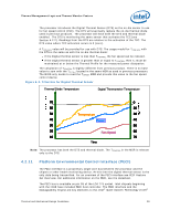
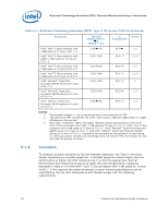
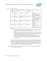
Balanced Technology Extended (BTX) Thermal/Mechanical Design Information 5 Balanced Technology Extended (BTX) Thermal/Mechanical Design Information 5.1 5.1.1 Overview of the Balanced Technology Extended (BTX) Reference Design The reference thermal module assembly is a Type II BTX compliant design and is compliant with the reference BTX motherboard keep-out and height recommendations defined Section 6.6. The solution comes as an integrated assembly. An isometric view of the assembly is provided Figure 5-4. Target Heatsink Performance Table 5-1 provides the target heatsink performance for the processor with the BTX boundary conditions. The results will be evaluated using the test procedure described in Section 5.2. The table also includes a TA assumption of 35.5 °C for the Intel reference thermal solution at the processor fan heatsink inlet discussed Section 3.3. The analysis assumes a uniform external ambient temperature to the chassis of 35 °C across the fan inlet, resulting in a temperature rise, TR, of 0.5 °C. Meeting TA and CA targets can maximize processor performance (refer to Sections 2.2, 2.4. and Chapter 4). Minimizing TR, can lead to improved acoustics. Thermal and Mechanical Design Guidelines 41
-
 1
1 -
2
-
3
-
4
-
5
-
6
-
7
-
8
-
9
-
10
-
11
-
12
-
13
-
14
-
15
-
16
-
17
-
18
-
19
-
20
-
21
-
22
-
23
-
24
-
25
-
26
-
27
-
28
-
29
-
30
-
31
-
32
-
33
-
34
-
35
-
 36
36 -
 37
37 -
 38
38 -
 39
39 -
 40
40 -
 41
41 -
 42
42 -
 43
43 -
 44
44 -
 45
45 -
 46
46 -
47
-
48
-
49
-
50
-
51
-
52
-
53
-
54
-
55
-
56
-
57
-
58
-
59
-
60
-
61
-
62
-
63
-
64
-
65
-
66
-
67
-
68
-
69
-
70
-
71
-
72
-
73
-
74
-
75
-
76
-
77
-
78
-
79
-
80
-
81
-
82
-
83
-
84
-
85
-
86
-
87
-
88
-
89
-
90
-
91
-
92
-
93
-
94
-
95
-
96
-
97
-
98
-
99
-
100
-
101
-
102
-
103
-
104
-
105
-
106
-
107
-
108
-
109
-
110
-
111
-
112
-
113
-
114
-
115
-
116
-
117
-
118
-
119
-
120
-
121
-
122
-
123
-
124
-
125
-
126
-
127
-
128
-
129
-
130
-
131
-
132
-
133
-
134
-
135
-
136
-
137
-
138
-
139
-
140
-
141
-
142
-
143
-
144
-
145
-
146
-
147
-
148
 |
 |
