Intel E6420 Design Guidelines - Page 82
Load Cell Installation in Machined Heatsink Base Pocket - Bottom View
 |
UPC - 735858192569
View all Intel E6420 manuals
Add to My Manuals
Save this manual to your list of manuals |
Page 82 highlights
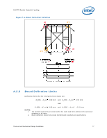
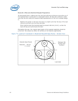
Heatsink Clip Load Metrology Remarks: Alternate Heatsink Sample Preparation As mentioned above, making sure that the load cells have minimum protrusion out of the heatsink base is paramount to meaningful results. An alternate method to make sure that the test setup will measure loads representative of the non-modified design is: Machine the pocket in the heat sink base to a depth such that the tips of the load cells are just flush with the heat sink base Then machine back the heatsink base by around 0.25 mm [0.01"], so that the load cell tips protrude beyond the base. Proceeding this way, the original stack height of the heatsink assembly should be preserved. This should not affect the stiffness of the heatsink significantly. Figure 7-8. Load Cell Installation in Machined Heatsink Base Pocket - Bottom View Heatsink Base Pocket Diameter ~ 29 mm [~1.15"] Package IHS Outline (Top Surface) Load Cells 82 Thermal and Mechanical Design Guidelines
-
 1
1 -
2
-
3
-
4
-
5
-
6
-
7
-
8
-
9
-
10
-
11
-
12
-
13
-
14
-
15
-
16
-
17
-
18
-
19
-
20
-
21
-
22
-
23
-
24
-
25
-
26
-
27
-
28
-
29
-
30
-
31
-
32
-
33
-
34
-
35
-
36
-
37
-
38
-
39
-
40
-
41
-
42
-
43
-
44
-
45
-
46
-
47
-
48
-
49
-
50
-
51
-
52
-
53
-
54
-
55
-
56
-
57
-
58
-
59
-
60
-
61
-
62
-
63
-
64
-
65
-
66
-
67
-
68
-
69
-
70
-
71
-
72
-
73
-
74
-
75
-
76
-
 77
77 -
 78
78 -
 79
79 -
 80
80 -
 81
81 -
 82
82 -
 83
83 -
 84
84 -
 85
85 -
 86
86 -
 87
87 -
88
-
89
-
90
-
91
-
92
-
93
-
94
-
95
-
96
-
97
-
98
-
99
-
100
-
101
-
102
-
103
-
104
-
105
-
106
-
107
-
108
-
109
-
110
-
111
-
112
-
113
-
114
-
115
-
116
-
117
-
118
-
119
-
120
-
121
-
122
-
123
-
124
-
125
-
126
-
127
-
128
-
129
-
130
-
131
-
132
-
133
-
134
-
135
-
136
-
137
-
138
-
139
-
140
-
141
-
142
-
143
-
144
-
145
-
146
-
147
-
148
 |
 |
