Intel E6420 Design Guidelines - Page 44
Effective Fan Curve
 |
UPC - 735858192569
View all Intel E6420 manuals
Add to My Manuals
Save this manual to your list of manuals |
Page 44 highlights
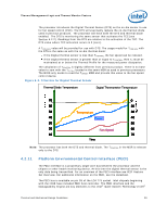
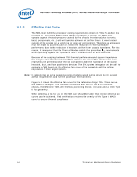
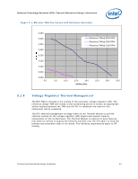
Balanced Technology Extended (BTX) Thermal/Mechanical Design Information 5.1.3 Effective Fan Curve The TMA must fulfill the processor cooling requirements shown in Table 5-1 when it is installed in a functional BTX system. When installed in a system, the TMA must operate against the backpressure created by the chassis impedance (due to vents, bezel, peripherals, etc...) and will operate at lower net airflow than if it were tested outside of the system on a bench top or open air environment. Therefore an allowance must be made to accommodate or predict the reduction in Thermal Module performance due to the reduction in heatsink airflow from chassis impedance. For this reason, it is required that the Thermal Module satisfy the prescribed CA requirements when operating against an impedance that is characteristic for BTX platforms. Because of the coupling between TMA thermal performance and system impedance, the designer should understand the TMA effective fan curve. This effective fan curve represents the performance of the fan component AND the impedance of the stator, heatsink, duct, and flow partitioning devices. The BTX system integrator will be able to evaluate a TMA based on the effective fan curve of the assembly and the airflow impedance of their target system. Note: It is likely that at some operating points the fans speed will be driven by the system airflow requirements and not the processor thermal limits. Figure 5-1 shows the effective fan curve for the reference design TMA. These curves are based on analysis. The boundary conditions used are the S2 6.9L reference chassis, the reference TMA with the flow portioning device, extrusion and an AVC Type II fan geometry. When selecting a fan for use in the TMA care should be taken that similar effective fan curves can be achieved. Final verification requires the overlay of the Type II MASI curve to ensure thermal compliance. 44 Thermal and Mechanical Design Guidelines
-
 1
1 -
2
-
3
-
4
-
5
-
6
-
7
-
8
-
9
-
10
-
11
-
12
-
13
-
14
-
15
-
16
-
17
-
18
-
19
-
20
-
21
-
22
-
23
-
24
-
25
-
26
-
27
-
28
-
29
-
30
-
31
-
32
-
33
-
34
-
35
-
36
-
37
-
38
-
 39
39 -
 40
40 -
 41
41 -
 42
42 -
 43
43 -
 44
44 -
 45
45 -
 46
46 -
 47
47 -
 48
48 -
 49
49 -
50
-
51
-
52
-
53
-
54
-
55
-
56
-
57
-
58
-
59
-
60
-
61
-
62
-
63
-
64
-
65
-
66
-
67
-
68
-
69
-
70
-
71
-
72
-
73
-
74
-
75
-
76
-
77
-
78
-
79
-
80
-
81
-
82
-
83
-
84
-
85
-
86
-
87
-
88
-
89
-
90
-
91
-
92
-
93
-
94
-
95
-
96
-
97
-
98
-
99
-
100
-
101
-
102
-
103
-
104
-
105
-
106
-
107
-
108
-
109
-
110
-
111
-
112
-
113
-
114
-
115
-
116
-
117
-
118
-
119
-
120
-
121
-
122
-
123
-
124
-
125
-
126
-
127
-
128
-
129
-
130
-
131
-
132
-
133
-
134
-
135
-
136
-
137
-
138
-
139
-
140
-
141
-
142
-
143
-
144
-
145
-
146
-
147
-
148
 |
 |
