Intel SE7221BK1-E User Guide - Page 18
Connector and Component Locations - e pci express
 |
UPC - 735858168656
View all Intel SE7221BK1-E manuals
Add to My Manuals
Save this manual to your list of manuals |
Page 18 highlights
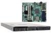
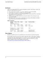
Server Board Features Intel® Entry Server Board SE7221BK1-E User Guide Connector and Component Locations The connections you make depend on the chassis and the components you are installing. AB C D EF GH I EE J DD CC CPU K BB AA Socket Z DIMM 1A Socket DIMM 2A Socket DIMM 1B Socket DIMM 2B Socket Y X W V U T S R QP O N ML TP01326 Figure 2. Intel® Entry Server Board SE7221BK1-E Connections A Chassis Intrusion Header B PCI Slot C PCI-X 100 SLOT D PCI-X 100 SLOT E PCI-Express* or Riser Connector Slot F +12v CPU Power G System Fan #1 (optional) H Back Panel I/O Connectors I System Fan #2 (optional) J CPU Fan (optional) K CPU Socket L DIMM Sockets (two - from left to right: DIMM 1B, DIMM 2B) M DIMM Sockets (two - from left to right: DIMM 1A, DIMM 2A) N Front USB Header (optional) O System Fan Headers (for Intel® Server Board SR1425BK1-E) P System Fan #4 Q System Fan #3 (optional) R Main Power Connector S Floppy Connector T IDE Connector U SATA 4 Connector V SATA 3 Connector W 34-pin Front Panel Connector X Serial ATA (SATA) 2 Connector Y SATA 1 Connector Z BIOS Control Jumper AA BIOS Select Jumper BB HDD LED Header CC HSBP Header DD Battery EE Serial B Header 4
-
 1
1 -
2
-
3
-
4
-
5
-
6
-
7
-
8
-
9
-
10
-
11
-
12
-
 13
13 -
 14
14 -
 15
15 -
 16
16 -
 17
17 -
 18
18 -
 19
19 -
 20
20 -
 21
21 -
 22
22 -
 23
23 -
24
-
25
-
26
-
27
-
28
-
29
-
30
-
31
-
32
-
33
-
34
-
35
-
36
-
37
-
38
-
39
-
40
-
41
-
42
-
43
-
44
-
45
-
46
-
47
-
48
-
49
-
50
-
51
-
52
-
53
-
54
-
55
-
56
-
57
-
58
-
59
-
60
-
61
 |
 |
