Intel SE7221BK1-E User Guide - Page 19
Configuration Jumpers - entry server board e
 |
UPC - 735858168656
View all Intel SE7221BK1-E manuals
Add to My Manuals
Save this manual to your list of manuals |
Page 19 highlights
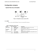
Intel® Entry Server Board SE7221BK1-E User Guide Configuration Jumpers System Recovery and Update Server Board Features Figure 3. Configuration Jumper Location (J1F2) ✏ NOTE Pin 1 is close to the SATA Header. This view is from the CPU side insert. Table 2. Configuration Jumper [J1F2] Function Pin - Pin Function CMOS CLEAR 1-2 MBMC control 2-3 Force erase PASSWORD CLEAR 5-6 Protect 6-7 Erase RECOVERY BOOT 9-10 10-11 Normal BOOT Recovery BOOT Description CMOS settings will be cleared on the next reset. Normal operation - Jumper 1-2 Administrator and user passwords will be cleared on the next reset. Normal operation - Jumper 5-6 BIOS recovery can be attempted by loading BIOS code into flash device from a floppy. 5
-
 1
1 -
2
-
3
-
4
-
5
-
6
-
7
-
8
-
9
-
10
-
11
-
12
-
13
-
 14
14 -
 15
15 -
 16
16 -
 17
17 -
 18
18 -
 19
19 -
 20
20 -
 21
21 -
 22
22 -
 23
23 -
 24
24 -
25
-
26
-
27
-
28
-
29
-
30
-
31
-
32
-
33
-
34
-
35
-
36
-
37
-
38
-
39
-
40
-
41
-
42
-
43
-
44
-
45
-
46
-
47
-
48
-
49
-
50
-
51
-
52
-
53
-
54
-
55
-
56
-
57
-
58
-
59
-
60
-
61
 |
 |

Intel® Entry Server Board SE7221BK1-E User Guide
Server Board Features
5
Configuration Jumpers
System Recovery and Update
Figure 3. Configuration Jumper Location (J1F2)
✏
NOTE
Pin 1 is close to the SATA Header. This view is from the CPU side insert.
Table 2. Configuration Jumper [J1F2]
Function
Pin – Pin Function
Description
1-2
MBMC control
CMOS CLEAR
2-3
Force erase
CMOS settings will be cleared on the next reset.
Normal operation – Jumper 1-2
5-6
Protect
PASSWORD
CLEAR
6-7
Erase
Administrator and user passwords will be cleared on the next
reset.
Normal operation – Jumper 5-6
9-10
Normal BOOT
RECOVERY BOOT
10-11
Recovery BOOT
BIOS recovery can be attempted by loading BIOS code into
flash device from a floppy.