Intermec CV61 CV61 Direct Wiring Kit Installation Instructions - Page 6
Assemble the Power Cable
 |
View all Intermec CV61 manuals
Add to My Manuals
Save this manual to your list of manuals |
Page 6 highlights
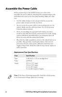
Assemble the Power Cable Before connecting to the forklift battery or to the CV61, assemble the power cable by attaching the terminal rings to the individual wires and to the fuse link assembly. Make sure that you: • Use the cable clamps or wire-ties provided to secure the power cable at least every 46 cm (18 in). • Do not secure the power cable to any moving parts on the vehicle. Make sure the cable is at least 15.2 cm (6 in) away from the exhaust system. • If you are installing on a gas-powered vehicle, you must install an On/Off switch with a minimum of 15 A DC rating, such as ITW (P/N 163-900-034) or an automatic shut-off device in series with the inline fuse holder. • Place the fuse link assembly as close to the vehicle battery as possible. This provides catastrophic failure short-circuit protection for the entire power cable and internal power supply of the CV61. If the fuse fails for any reason, replace it with a new fuse. Replacement Fuse Specifications Fuse Type Volts Amps Specification 3 AB (0.25 x 1.25 in catridge fuse) 250 VDC 20 A to 12 V input 10 A to 14 V input 6 A to 36 V input 5 A to 48 V input or higher Note: If the fuse is blowing repeatedly, check the vehicle power to see if excessive voltage spikes are occuring. 6 CV61 Direct Wiring Kit Installation Instructions
-
 1
1 -
 2
2 -
 3
3 -
 4
4 -
 5
5 -
 6
6 -
 7
7 -
 8
8 -
 9
9 -
 10
10 -
 11
11 -
 12
12
 |
 |
