Kenmore 4101 Installation Instructions
Kenmore 4101 - Elite 30 in. Slide-In Electric Range Manual
 |
View all Kenmore 4101 manuals
Add to My Manuals
Save this manual to your list of manuals |
Kenmore 4101 manual content summary:
- Kenmore 4101 | Installation Instructions - Page 1
appliance. Q Do not touch any electrkal switch; do not use any phone in your building. Q Immediately call your gas supplier from a neighbor's phone. Follow the gas supplier's instructions. Q If you cannot reach your gas supplier, call the fire department. Installation and service OF RANGE (C0untert0p - Kenmore 4101 | Installation Instructions - Page 2
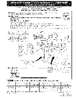
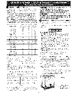
when the cabinet is unprotected. For cutouts below 22 7/8"(58.1 cm), appliance will slightly show out of the cabinet. Allow at least 19 ¼" ( WIDTH I G, COOKTOP J J D; DEPTH TO E; CUTOUT WIDTH *** I WIDTH I FRONT OF RANGE I(C°untert°P and Cab net F. CUTOUT a G. HEIGHT 30" (76,2 cm) 31Y2" ( - Kenmore 4101 | Installation Instructions - Page 3
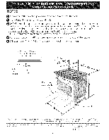
could cause glass breakage voiding the warranty. Level the unit if needed. After the installation, MAKE SURE that the uni is supported by the leveling legs NOT by the cooktop. "To successfully install the range, the initial level height from floor to underside of cooktop glass should be at least - Kenmore 4101 | Installation Instructions - Page 4
. elevations above see level, appliance rating shall be reduced by 4 percent for each additional 1000 ft. Important Note to the Consumer Keep these instructions with your Use & Care Guide for future reference. I RTANT SAFETY INSTRUCTIONS Installation of this range must conform with local codes - Kenmore 4101 | Installation Instructions - Page 5
3). Do not loosen the nuts which secure the factory-installed range wiring to terminal block while connecting range. Electrical failure or loss of electrical connection may occur. Electrical Connection to the Range This appliance is manufactured with the neutral terminal connected to the frame - Kenmore 4101 | Installation Instructions - Page 6
(access cover) upward to expose range terminal connection block (see figure 2). 2. installed at this location To 240 V receptacle NOTE: Be sure to remove the supplied _l grounding strap Figure 4 Direct Electrical Connection to the Circuit Breaker, Fuse Box or Junction Box If the appliance - Kenmore 4101 | Installation Instructions - Page 7
appliance cable wires. 3. In the circuit breaker, fuse box or junction box: connect appliance " (76,4 cm), reduce the 3A,, (1.9 cm) dimension. Countertop must be level, Place a level on the the range. If there is cabinet storage space above range, reduce risk by installing a range hood - Kenmore 4101 | Installation Instructions - Page 8
Pressure Regulator The regulator is already installed on the appliance. Do not make the connection too pressure regulator in the following order: 1. manual shutoff valve (not supplied) 2. 1/2" on the range, allow sufficient slack to pull the range outside the cutout for cleaning or servicing. NOTE: - Kenmore 4101 | Installation Instructions - Page 9
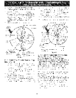
breakers at the main power source, and turn off the manual gas shut-off valve. Make sure the range is cold. Remove the service drawer CheckforleaksA. fterconnectinthgerangetothegassupply, (warmer drawer on some models) and open the oven door. chectkhesystemforleakws itha manometeIfra. manometer - Kenmore 4101 | Installation Instructions - Page 10
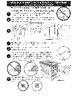
Important Note: Door removal is not a requirement for installation of the range, but is an added convenience. Refer to the Use and Care Guide for oven door removal instructions. Position range in front of the cabinet opening. Make sure that the glass which overhangs the countertop clears - Kenmore 4101 | Installation Instructions - Page 11
Refer to the Use and Care Guide packaged with the range for operating instructions and for care and cleaning of your range. Do not touch the elements or burners. They may be hot enough to cause burns. Remove all packaging from the oven before testing. 1.Install Burner Bases and Burner Caps This - Kenmore 4101 | Installation Instructions - Page 12
You Call for Service Read the Before You Call Checklist and operating instructions in your Use and Care Guide. It may save knobi,nseratthin-bladesdcrewdriveirntothehollowvalve stemandengagteheslottedscrewinsideF.lamseizecanbe increaseodrdecreaswediththeturnofthescrewA. djust you time and expense - Kenmore 4101 | Installation Instructions - Page 13
-Tip Brackets Installation instructions To reduce the risk of tipping of the range, the range must be secured to the floor by properly installed anti-tip bracket and screws packed with the range. Those parts are located in the oven. Failure to install the anti-tip bracket will allow the range to - Kenmore 4101 | Installation Instructions - Page 14
de 2" a 4" (5.1 1. Lea todas las instrucciones contenidas en este manual antes de instalar la estufa. 2. Saque todo el material usado en el los c6digos y reglamentos pertinentes. 4. Deje estas instrucciones con el comprador. No instale la unidad en el gabinete si no ha leido esta 2 p_iginas. A. - Kenmore 4101 | Installation Instructions - Page 15
libre para la profundidad cuando este abierta. 22 7/8" (58.1 cm) min. 23 1/4" (59.05 cm) max. ÷ (yea la nota 4) ÷ r de la puerta m PARTE DELANTERA DEL ARMARIO 1 1/8" _(2.86 cm) F Ref. 21¾" (55.25 cm)_ 1 Puerta abierta (vea la nota 5) A Panel lateral A: ALTURA B, ANCHO C: ANCHO DELA - Kenmore 4101 | Installation Instructions - Page 16
Ilustraci0n 1 / Deslice la unidad hacia el gabinete. Aseg0rese que la unidad este centrada con el centro de la abertura del gabinete. Remueva la parte en pl_istico extruido en cada lado de la cubierta de vidrio. (Algunos modelos) Es imprescindible que el reborde de metal que se encuentra debajo - Kenmore 4101 | Installation Instructions - Page 17
de seguridad que usted debe seguir. Estas set,in encontradas en el Manual del Usuario, lealo cuidadosamente. • Asegurese de que la estufa sea instalada , tftulo 24, HUD (parte 280)] o cuando tal estandar no se aplica, el Standard for Manufactured Home Installation 1982 (Manufactured Home sites - Kenmore 4101 | Installation Instructions - Page 18
la Estufa Este aparato se fabrica con el terminal neutro conectado al marco. Refiere al diagrama de alambraje en las paginas de centro de este manual. Para las casas sobre ruedas, las nuevas instalaciones, en los veh[culos de recreacion o en las _ireas donde los codigos locales no permiten la - Kenmore 4101 | Installation Instructions - Page 19
de tierra del marco con el alambre neutro del cord6n electrico de cobre (vea Figura 3): 1. Quite los tres tornillos en la parte m_is baja del panel trasero, luego levante la parte m_is baja del panel trasero (la cubierta de acceso) exponiendo el bloque de conexiones de los terminales de la estufa - Kenmore 4101 | Installation Instructions - Page 20
Conexion electrica directa ai cortadrcuito, a ia caja de fusibles o ia caja de empaimes Si el aparato est_qconectado directamente al cortacircuito, a la caja de fusibles o a la caja de empalmes, use un cable blindado flexible o no metalico recubierto de cobre (con alambre a tierra). Provee una - Kenmore 4101 | Installation Instructions - Page 21
del Recorte de el 29"(73.7 cm) (Figura 8): 2 3116" 2 3116" (5.56 cm) (73.7 cm) J Quite el 2 3/16" de material de frente a la parte posteriora. 1W' (3.2 cm) 31W' (80 cm) _:igura 8 Mostrador moldeado o enazulejo recortado 3/4" (1.9 cm) hacia atr_s en las esquinas de frente de la abertura del - Kenmore 4101 | Installation Instructions - Page 22
9 UBICAClON DEL REGULADOR DE PRESION V lvula de cierre Abierta Figura 11 La linea del suministro se debe de ser equipada de una wilvula de cierre manual aprobada. Esta wilvula se debe Iocalizar en el mismo cuarto que la estufa y debe estar en una Iocalizaci0n que permita la facilidad de la abertura - Kenmore 4101 | Installation Instructions - Page 23
La mudanza del aparato para reparaciones o [impieza Apague la corriente electrica a la estufa a la fuente de poder principal, y apague la wilvula de cierre manual de gas. AsegOrese de que la estufa este fresca. Quite el cajon de servicio (el cajon calentador en algunos modelos) y abre la puerta del - Kenmore 4101 | Installation Instructions - Page 24
esten verticales y alineados antes de instalar la plancha de cocinar. Lije el horde del mostrador para obtener las 31 1/2 (81 cm)" en la parte superior del mostrador. Instale las puertas del armario a 31 " (78,7 cm) de espacio entre elias para que no interfieran con la abertura de la puerta de la - Kenmore 4101 | Installation Instructions - Page 25
Figura 14 Comprobacion del Funcionamiento Consulte el Manual del Usuario inclufdo con la estufa para de la unidad antes de comprobarla. 1. Instale las tapas de los quemadores y de entre el piso y la superficie debajo del marco de la parte superior de la cocina. 5. Marque la distancia sobre la pared - Kenmore 4101 | Installation Instructions - Page 26
presion a la cual fue ajustada la estufa en la f_ibrica. Antes de Llarnar al Servicio Lea la seccion Evite Llamadas de Servicio en su Manual del Usuario. Esto le podr_i ahorrar tiempo y gastos. Esta lista incluye ocurrencias comunes que no son el resultado de defectos de materiales o fabricacion de - Kenmore 4101 | Installation Instructions - Page 27
una linea central en el piso donde se instalar_ la cocina. Si no hay pared posterior, dibujar otra linea en el piso que corresponda a la parte posterior de la cocina. 2. Desplegar el molde de papel y colocarlo alisado sobre el piso con el v#rtice posterior derecho posicionado exactamente en la - Kenmore 4101 | Installation Instructions - Page 28
B'ALLUMAGE BRULEUR W-23 _ _, OUEMADOR BOUGIE TOP BURNER DE ENCENDIDO SUPERIOR D'ALLUMAGE BRULEUR CAUTION: DISCONNECT POWER BEFORE SERVICING UNIT. ATENCION:CORTAR LA CORIENTE ANTES DE REALIZAR EL _NTENIMIENTO DEL ELECTRODOMESTICO. ATTENTION:COUPEZ L'ALIMENTATION AVANT D'EFFECTUER LA
-
 1
1 -
 2
2 -
 3
3 -
 4
4 -
 5
5 -
 6
6 -
 7
7 -
8
-
9
-
10
-
11
-
12
-
13
-
14
-
15
-
16
-
17
-
18
-
19
-
20
-
21
-
22
-
23
-
24
-
25
-
26
-
27
-
28
 |
 |
iNSTALLATiON
AND
SERVICE
MUST BE PERFORMED BY A QUALIFIED
iNSTALLER.
IMPORTANT:
SAVE FOR LOCAL
ELECTRICAL
INSPECTOR'S USE.
READ AND SAVE THESE INSTRUCTIONS FOR FUTURE REFERENCE.
m
Q
Q
Q
Q
if the information
in
this
manual
is
not followed
exactly,
a fire
or
explosion
may result
causing
property
damage,
personal
injury
or death.
FOR YOUR SAFETY:
--
Do not store or use gasoline or other flammable
vapors and liquids in the vicinity of this or any
other appliance.
WHAT TO DO IF YOU SMELL GAS:
Do not try
to light
any appliance.
Do not touch
any electrkal
switch;
do not use any phone
in
your
building.
Immediately
call your
gas supplier
from
a neighbor's
phone.
Follow
the gas supplier's
instructions.
If you cannot
reach your
gas supplier,
call the fire
department.
Installation
and service
must
be performed
by a qualified
installer,
service
agency
or the gas supplier.
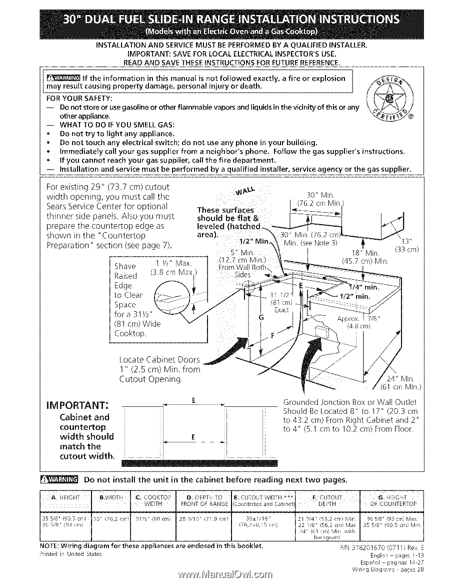
For existing 29"
(73.7 cm) cutout
width
opening,
you must call the
Sears Service Center for optional
thinner
side panels. Also you must
prepare the countertop
edge as
shown
in the
"Countertop
Preparation"
section
(see page 7).
Shave
Raised
Edge
to
Clear
Space
fora
31Y2"
(81 cm) Wide
Cooktop.
1 1/2" Max
(3.8
cm Max
These
surfaces
should
be flat
&
leveled
(hatched_
area).
112" Mi
5"
Vlin.
Sides
30" Min.
(76.2 cm Min.
30"
Min. (76.2
18" Min.
(45.7 cm) Min.
it
(33 cm)
Locate
Cabinet
Doors
1"
(2.5
cm)
Min.
from
Cutout
Opening.
IM PORTANT:
Cabinet
and
countertop
width
should
match
the
cutout
width.
_
.................................................................
i[
...................................................................
24" Min.
I
(61 cm Min.)
Grounded
Jonction
Box or Wall
Outlet
Should
Be Located
8"
to
17"
(20.3
cm
to 43.2
cm) From Right
Cabinet
and 2"
to 4"
(5.1 cm to
10.2 cm) From Floor.
Do
not
install
the
unit
in the
cabinet
before
reading
next
two
pages.
A.
HE!GHT
I
B.WIDTH.
(:,COOKFOp
[:);DEPTH
TO
E:
CUTOUT
W!DTH ***
I:.CUTOUT
HEIGHT
G:
I
!
WIDTH
.
FRONT OF RANGE
(C0untert0p and Cabine!
DEPTH
.
OF COUNTERTOP
35 5/8"
(90.5cm)-
30"
(76,2
cm)
311/2 '' (80cm)
28
5/16"
(71,9
cm)
30_+1/16"
21 3/4"
(55,2
cm)
Min.
36 5/8"
(93cm)
Max.
36
5/8"
(93
cm)
(76,2_+0,15
cm)
22
1/8"
(56,2
cm) Max
35
5/8"
(90.5
cm)
Min.
24"
(61
cm)
Min.
with
backguard
NOTE:Wiring diagram for these appliances are enclosed in this booklet.
P/N 318201670 (0711) Rev.
Printed
in
United
States
English-
pages
1-13
Espahol-
p_iginas 14-27
Wiring
Diagrams
- pages
28